@TangWill
2020-04-15T08:25:20.000000Z
字数 175484
阅读 3035
Software Engineering
SE
- Software Engineering
- Chapter 1 The Nature of Software
- 1.1 What is Software?
- 1.2 Why need Document?
- 1.3 Software Documentation
- 1.4 Differnct characteristics between software and hardware
- 1.5 Features of Software
- 1.6 Software Application Domain
- 1.7 Legacy Software(遗留软件)
- 1.8 Essential Attributes of Good Software
- 1.9 Software Crisis
- 1.10 What are the reasons for the software crisis?
- 1.11 Bad Experiences in SD
- 1.12 How to solve Software Crisis
- Chapter 2 Software Engineering
- Chapter 3 Software Process Structure
- Chapter 4 Process Models
- Chapter 7 Understanding Requirements
- Chapter 8 Requirements Modeling: Scenario Methods
- 8.1 Requirements Analysis
- 8.2 Requirements Modeling
- 8.3 Requirements Models
- 8.4 Overall Objectives and Philosophy
- 8.5 Analysis Rules of Thumb
- 8.6 Domain Analysis and Analysis Pattern
- 8.7 Domain Analyst (域分析师)
- 8.8 Requirements Modeling Approaches
- 8.9 Graphical Modeling Languages
- 8.10 Three types of Modeling Method
- 8.11 Scenario-Based Modeling
- 8.12 Use Case Diagram
- 8.13 Conclusion for Scenario-Based Modeling
- 8.14 Behavioral Mode - activity diagram
- 8.15 Behavioral Models--Swimlane Diagrams
- Chapter 9 Class-based Modeling
- Chapter 10 Requirements Modeling:Behavioral Models
- Chapter 11 Design Concepts
- 11.1 Overall of Design Concepts
- 11.2 What is the work product of Design?
- 11.3 How do I ensure that I’ve done it right?
- 11.4 Software design
- 11.5 Design Within the context of Software Engineering
- 11.6 Why design is so important?
- 11.7 The Design Process
- 11.8 Software Quality Guidelines and Attributes
- 11.9 Design concepts
- 11.10 The Design Model
- 11.11 Design Model Elements
- Chapter 12 Architectural Design
- 12.1 The concept of Architectural Design
- 12.2 Who does Architectural Design?
- 12.3 Why is Architectural Design important?
- 12.4 What is the work product?
- 12.5 How do I ensure that I’ve done it right?
- 12.6 Architectural Design
- 12.7 Software Architecture
- 12.8 Architectural Genres(类型)
- 12.9 Architectural Styles
- 12.10 A Brief Taxonomy of Architectural Styles
- Chapter 15 Quality Concepts
- Chapter 16 Software Quality Assurance
- 16.1 SQA
- 16.2 Elements of SQA
- 16.3 SQA Tasks
- 16.3.1 Prepares an SQA plan for a project.
- 16.3.2 Participates in the development of the project’s software process description.
- 16.3.3 Reviews software engineering activities to verify compliance with the defined software process.
- 16.3.4 Audits designated software work products to verify compliance with those defined as part of the software process.
- 16.3.5 Ensures that deviations in software work and work products are documented and handled according to a documented procedure.
- 16.3.6 Records any noncompliance and reports to senior management.
- 16.4 SQA Goals
- 16.5 Statistical SQA
- 16.6 Six-Sigma for Software Engineering
- 16.7 Software Reliability
- 16.8 Measures of Reliability & Availability
- 16.9 Software safety
- 16.10 The ISO 9000 Quality Standard
- 16.11 The SQA Plan
- 16.12 A Framework for Product Metrics
- Chapter 17 Software Testing Strategies
- Chapter 18 Testing Conventional Application
- Chapter 22 Project Managemen Concepts
- Chapter 23 Process and Projec Metrics
- Chapter 24 Estimation for Software Projects
- Chapter 25 Project Scheduling
- Chapter 26 Risk Management
- Refrence of Northeastern University
- R1 Use Case Modeling
- R2 Use Case Diagram
- R2.1 Use-Case Diagram of Elevator Problem
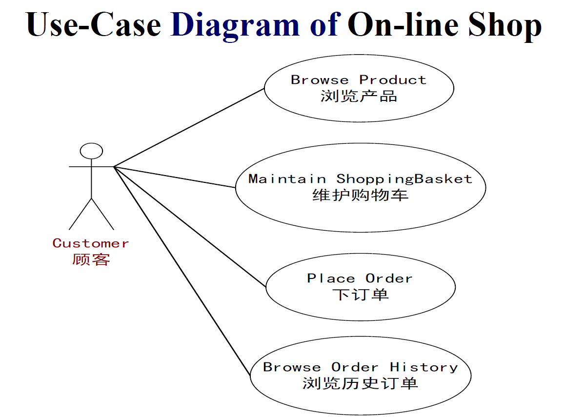
- R2.2 Use-Case Diagram of On-line Shop
- R2.3 Use-Case Diagram of Course Regisration System
- R2.4 Use-Case Specification
- R2.5 The Relationship between Actors(Generalization & Agency)
- R2.6 The Relationship between use cases(Generalization & Inclusion & Extension)
- R3 Class Diagram
- R4 Dynamic Modeling
- Appendix of abbreviation
- Chapter 1 The Nature of Software
Chapter 1 The Nature of Software
1.1 What is Software?
Software is:
- instructions (computer programs) that when executed provide desired features, function, and performance;
- data structures that enable the programs to adequately manipulate information and
- documentation that describes the operation and use of the programs.
1.2 Why need Document?
- Improve the visibility on software process
- Develop more efficiently
- Mark the outcome and the end of one certain period for developers (milestone)
- Record technical information during the development
- Provide information on software operation, maintenance, and training
- Help users to understand software functions
1.3 Software Documentation
- Feasibility analysis report (可行性分析报告)
- Software requirement specification (软件需求规格说明)
- Data requirement specification(数据需求规格说明)
- Project development plan(项目开发计划)
- Testing plan(测试方案)
- Conceptual (Architectural) design document(概念设计文档)
- Detailed design document(详细设计文档)
- Database design document (数据库设计文档)
- Module development files(模块开发文件)
- User manual(用户手册)
- Software instruction manual(软件指令手册)
- Testing analysis report(测试分析报告)
- Project development summary report (项目开发总结报告)
1.4 Differnct characteristics between software and hardware
Software is developed or engineered, it is not manufactured in the classical sense.
Software doesn't “wear out."
Although the industry is moving toward component-based construction, most software continues to be custom-built.However, hardware is manufactured using existing mould.
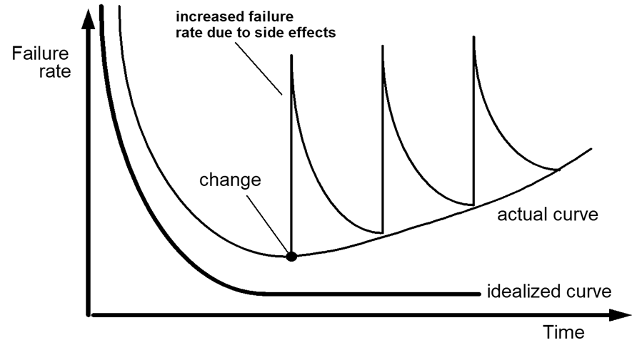
Software doesn’t wear out,but it does deteriorate!
1.5 Features of Software
Complexity
Linux 630 functions, 1814 function-call
Conformity
different environment, ensure to conform
Software can not exist independently, it need to rely on a certain environment (hardware, network ,other software)
Software must conform to some existing convention (惯例) and technology and system.
Software need to conform to other interfaces which can not be redesigned.
Changeability
requirements always change
Invisibility
invisible, unvisualizable, untouchable
Software is invisible, unvisualizable and untouchable logical entity,
Developer could see the program code, but the program code is not the software itself.
Software runs in the form of machine code, but developer could not see how source code is executed.
1.6 Software Application Domain
- System software
- Application software
stand-alone programs that solve a specific business need - Engineering/scientific software
- Embedded software
- Product-line software
- WebApps (Web applications)
- Artificial intelligence software
- System software - a collection of programs written to service other programs.
- Operating system components
- drivers
- telecommunications processors
- Compilers(编译器)
- Editors
- file management utilities
- DBMS 数据库
1.7 Legacy Software(遗留软件)
legacy software (Legacy system)has the following features:
Longevity
It have been running for a long time.
Business criticality
- Still in use now.
- Business will stop without it.
- It is very important for users.
poor quality
It can not satisfy all needs of users.
If the legacy software meets the needs of its users and runs reliably, it is not broken and dose not need to be fixed.
However, as time passes, legacy system often evolve for one or more of the following reasons:
- software must be adapted to meet the needs of new computing environments or technology.
- software must be enhanced to implement new business requirements.
- software must be extended to make it interoperable with other more modern systems or databases.
- software must be re-architected to make it viable within a evolving computing environment.
It must be reengineered so that it remains viable in the future.
1.8 Essential Attributes of Good Software
Good Software means high-quality software.
Not only quality is concerned with what the software does (functional 功能性).
But also it is reflected in so-called quality or non-functional (非功能性)software attributes,such as
- the software’s response time to a user query
- the understandability of the program code
| Product characteristic | Decription |
|---|---|
| Maintainability | Should be written in such a way so that it can evolve to meet the changing needs of customers. Because software change is an inevitable requirement of a changing business environment. |
| Dependability&security | Includes reliability, security and safety. Dependable software should not cause physical or economic damage in the event of system failure. Malicious users should not be able to access or damage the system. |
| Efficiency | Should not make wasteful use of system resources such as memory and processor cycles. Efficiency includes responsiveness, processing time, memory utilisation, etc. |
| Acceptability | Must be acceptable to the type of users for which it is designed. Must be understandable, usable and compatible with other systems that they use. |
1.9 Software Crisis
Back in the 1960’s, hardware was much more expensive than software
More and more software projects failed.
- to be late,
- over budget
- many faults(bugs)
- not meet client’s needs
The term "software crisis" appeared and has been used since the late 1960s to describe those recurring system development problems in which software development problems cause the entire system
The crisis manifested itself in several ways:
- Projects running over-budget.
- Projects running over-time.
- Software was very inefficient.
- Software was of low quality.
- Software often did not meet requirements.
- Software quality is usually unreliable.
- Projects were unmanageable and code difficult to maintain. (difficult to modify, add new - function, reuse)
- Software was never delivered.
1.10 What are the reasons for the software crisis?
- Rolling baseline(摆动的极限,即需求不确定)
Shorter development cycles are business requirements
Initial requirements usually poorly defined - Software complexity
Business software demands are increasing
No one understands the entire system
Legacy systems must be maintained, but the original developers are gone - Failure to manage risk
The waterfall lifecycle can delay problem identification
There is no proof that the system will run until late in the lifecycle
The result is maximum risk
1.11 Bad Experiences in SD
- Customers are too busy to spend time working with analysts or developers on their requirements.
- User surrogates such as marketing or managers claim to speak for the user, but they really don’t know the business details.
- Customers claim all the requirements are critical, so they do not prioritize them.
- Developers encounter ambiguities and missing information when coding, so they have to guess.
- Customers sign off (签字认可) on the requirements and make changes continuously.
- The project scope increases as requirements changes, but schedule slips (进度缓慢) because no more resources are provided.
- Functionality/Features are requested, but never used.
- The specification is satisfied, but the customer is not.
- System design is not well documented and the original designer has left the team;
- Source code is not well formatted, which introduces extra maintenance cost;
- Late found bugs result in budget overrun;
- Customers complains of leaked bugs;
- System becomes more and more complex while user satisfaction is getting down.
- Schedule slipping, budget burnt out.
1.12 How to solve Software Crisis
The main way out is to develop Software following the engineered principle and methods,
including:
- Good organization
- Rigorous management
- Multiple developers collaboration
- Efficient technique, methods and tools
Chapter 2 Software Engineering
It was meant to solve "software crisis".
2.1 Software Engineering
Software Engineering: an engineering discipline focus on study how to well develop and maintain software from technique and management perspectives.
SE is an engineering discipline that is concerned with all aspects of software production from the early stages of system specification through to maintaining the system after it has gone into use.
Engineering discipline
Using appropriate theories and methods to solve problems under the organizational and financial constraints(e.g., cost and deadline).
All aspects of software production
Not just technical process of development.
But also project management and the development of tools, methods etc. to support software production.
The IEEE definition
Software Engineering
(1) The application of a systematic, disciplined, quantifiable approach to the development, operation, and maintenance of software; that is, the application of engineering to software.
(2) The study of approaches as in (1).
2.2 SE is a Layered Technology
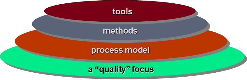
Any engineering approach (including SE) must rest on the commitment to quality. The foundation for software engineering is the process layer.
A quality focus:
Every organization rests on its commitment to quality.
Total quality management ultimately lead to development of increasingly more effective approaches to software engineering.
The bedrock that supports software engineering is a quality focus.
Process:
It’s a foundation layer for software engineering.
It defines framework that must be established for effective delivery of software engineering technology.
It forms the basis for management control of software projects and establishes the context in which technical methods are applied, work products (models, documents, data, reports, form, etc.) are produced.
Methods:
It provides the technical how-to's for building software.
Methods encompass a broad array of tasks that include requirements analysis, design, program construction, testing, and support.
Methods rely on a set of principles that govern each area of the technology and include modelling activities and other descriptive techniques(text or diagram).
Tools:
Provide automated or semi-automated support for the process, methods and quality control.
When tools are integrated so that information created by one tool can be used by another, a system for the support of software development, called computer-aided software engineering (CASE)
To sum up, SE includes:
Process
Foundation. Defines a framework that must be established for effective delivery of software engineering technology.
Methods
It provides the technical how-to’s for building software.
Encompass a broad array of tasks including communication, requirements analysis, design modeling, program construction, testing and support
Tools
Provide automated or semi-automated support for the process and methods.
2.3 Importance of SE
SE is important for two reasons:
1. More and more, individuals and society rely on advanced software systems.
We need to be able to produce reliable and trustworthy systems economically and quickly.
2. It is usually cheaper, in the long run, to use software engineering methods and techniques for software systems rather than just write the programs as if it was a personal programming project.
For most types of system, the majority of costs are the costs of changing the software after it has gone into use.
or
1. It enable us to build complex systems in a timely manner and with high quality.
2. It impose discipline to work that can become quite chaotic,but it also allows the people who build computer software to adapt their approach in a manner that best suits their need.
2.4 Goals of Software Engineering
Correctness
No errors
Usefulness
Does what we want it to do
Minimal production effort
- minimal cost
- minimal time
- maximum profit
Minimal maintenance effort
The maintenance of existing software can account for over 60% of all effort expended by a development organization, and the percentage continues to rise as more software is producrd. It is the most costly phase of the software life cycle.
2.5 Frequently Asked Questions about Software Engineering
| Question | Answer |
|---|---|
| What is software? | Computer programs, data and associated documentation. Software products may be developed for a particular customer or may be developed for a general market. |
| What are the attributes of good software? | Good software should deliver the required functionality and performance to the user and should be maintainable, dependable, efficient, and acceptable. |
| What is software engineering? | Software engineering is an engineering discipline that is concerned with all aspects of software production. |
| What is the difference between software engineering and computer science? | Computer science focuses on theory and fundamentals; software engineering is concerned with the practicalities of developing and delivering useful software. |
| What is the difference between software engineering and system engineering? | System engineering is concerned with all aspects of computer-based systems development including hardware, software and process engineering. Software engineering is part of this more general process. |
| What are the key challenges facing software engineering? | Coping with increasing diversity, demands for reduced delivery times and developing trustworthy software. |
| What are the costs of software engineering? | Roughly 60% of software costs are development costs, 40% are testing costs. For custom software, evolution costs often exceed development costs. |
| What are the best software engineering techniques and methods? | While all software projects have to be professionally managed and developed, different techniques are appropriate for different types of system. For example, games should always be developed using a series of prototypes whereas safety critical control systems require a complete and analyzable specification to be developed. You can’t, therefore, say that one method is better than another. |
| What differences has the web made to software engineering? | The web has led to the availability of software services and the possibility of developing highly distributed service-based systems. Web-based systems development has led to important advances in programming languages and software reuse. |
Chapter 3 Software Process Structure
3.1 Definition of Software Process
SP is a framework for the activities, actions and tasks that are required to build high- quality software.
- An activity strives to achieve a broad objective(e.g.,communication with stakeholders) and is applied.
- An action(e.g., architectural design) encompasses a set of tasks that produce a major work product(e.g., an architectural model).
- A task focuses on a small, but well-defined
objectives(e.g., conducting a unit test) that produces a tangible outcome.
3.2 Intent of software process
To deliver software in a timely manner and with high quality to satisfy those who have sponsored its creation and those who will use it.
The elements of a SP are activities, actions and tasks.
A process defines who is doing what, when and how to reach a certain goal.
3.3 Software Life Cycle(SLC)
Software Process model is an abstract representation of a software process.
Software process model is also called Software Life Cycle model.
软件过程模型、软件生存期模型、软件生命周期模型.
A software life cycle model depicts (描述)the significant phases or activities of a software project from conception (设想,构想) until the product is retired(退役).
It specifies the relationships between project phases.
A software life cycle includes 3 periods:
- software definition (软件定义)
- software development (软件开发)
- operation and maintenance (运行维护)
which are then decomposed into 11 phases.
Software definition
- Problem definition (问题定义)
What should we do? What problem should we solve? - Feasibility study(可行性研究)
Whether we should produce the system?What are the benefit of the software? - Requirement analysis (需求分析)
what function should the software provide to the users?
Software development
- Conceptual design (概念设计、总体设计)
General design, the functionality architecture, ER model if using DB - Detailed design (详细设计)
design for each module, the table design for DB - Implementation (实现,Coding & Unit testing)
programming or coding and testing each module to check whether it is correct. - Integration testing (集成测试)
put all modules together and test the module interfaces - System testing (系统测试)
Besides the functions of software, non-function testing(performance testing ) need to be done.
Operation & Maintenance
- Operation (运行)
users run the system formally. - Maintenance (维护)
Software maintenance is, far more than "fixing mistakes".
Software maintenance is the most costly phase of the software life cycle.
Software maintenance is undertaken after a program is released for use.
we defined four different maintenance activities:
- corrective maintenance,
- adaptive maintenance(upgrade/hardware or system software),
- perfective maintenance or enhancement(add functions),
- and preventive maintenance or reengineering(目前没发现bug,预测之后会有错误发生,提前修复他).
- Retirement (退役)
The software is no use and abandoned.
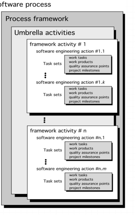
3.4 Process framework(PF)
PF establishes the foundation for a complete software engineering process.
PF identifies a small number of framework activities that are applicable to all software
projects, regardless of their size or complexity.
PF encompasses a set of umbrella activities that are applicable across the entire software
process.
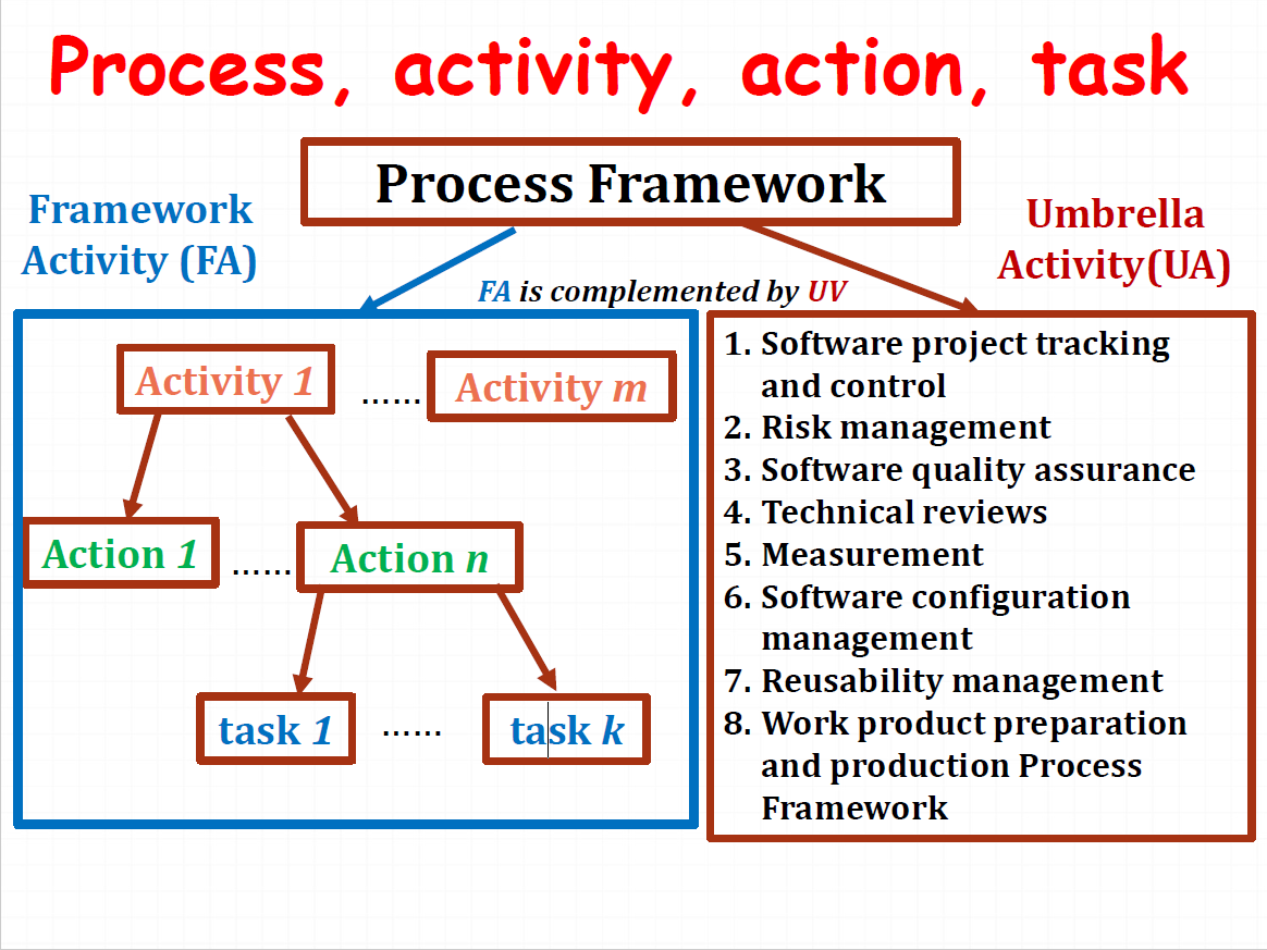
Framework activities are complemented (补充) by a number of umbrella activities.
3.5 Framework Activities
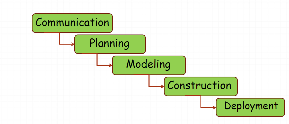
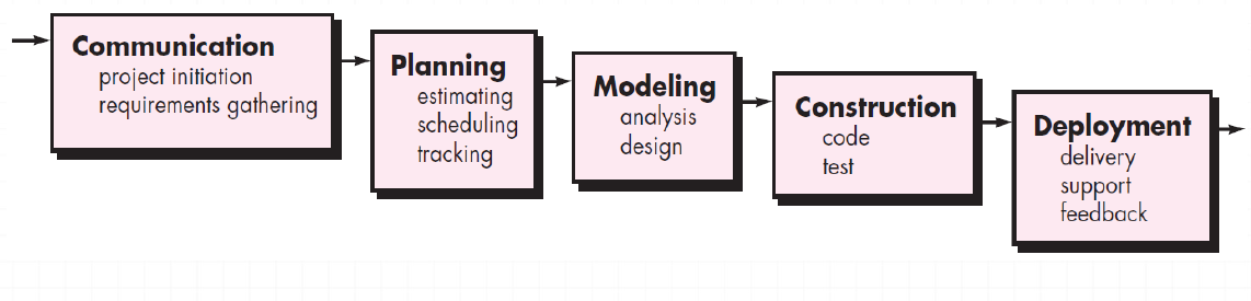
A generic (通用的)process framework for SE encompasses five activities:
- Communication (Requirements collection) 问题定义/需求获取
- Planning (策划,Software project plan,项目计划)
- Modeling (Analysis and Design,软件建模)
- Construction (implementation and testing,软件构建)
- Deployment ( Delivery and feedback,软件部署)
Communication
Important to communicate and collaborate with customers(and other stakeholders 干系人).
A stakeholder is anyone who has a stake in the successful outcome of the project – business manager, end users, software engineers, support people, etc.
The intent is to understand stakeholders’ objectives for the project and to gather requirements.
Planning
Any complicated journey can be simplified if a map exists.A software project is a complicated journey. Planning activity creates a “map” that helps guide the team as it makes the journey.
The map—called a software project plan--- defines the software engineering work by describing the technical tasks, the risk, the required resources, the work products to be produced and a work schedule.
Modeling
The model is the big picture of the thing that you want to create.
It can help developer and customer to better understand requirements (Analysis of requirements & Design of software)
Construction
Code generation: either manual or automated or both
Testing – to uncover error in the code.
Deployment
Delivery to the customer for evaluation(评测)
Customer provide feedback based on the evaluation.
3.6 Umbrella Activities
In Software engineering process, a number of umbrella activities are complement to (补充) the
framework activities.
In general, umbrella activities are applied throughout (贯穿)a software project and help
a software team manage and control the progresses, quality, change, and risk.
Typical umbrella activities include:
- Software project tracking and control
Assess progress against the project plan.
Take necessary action to maintain schedule. - Risk management
Assesses risks that may effect that outcome of project or quality of product. - Software quality assurance
Defines and conducts the activities required to ensure software quality. - Technical reviews
Assess software engineering work products in an effort to uncover and remove errors before they are propagated to the next activity. - Measurement
- Defines and collects process, project, and product measures
- Assist the team in delivering software that meets customer ’s needs.
- Can be used in conjunction with all other framework and umbrella activities.
可以与所有其他框架和普适性活动结合使用
- Software configuration management
Manages the effects of change. - Reusability management
- Define criteria for work product reuse.
- Establish mechanisms to achieve reusable components.
- Work product preparation and production
Include the activities required to create work products such as models, documents, logs, forms and lists.
3.7 Process and SE
Is “process” synonymous with “software engineering”?
Yes and no.
Software process defines the approach that is taken as software is engineered.But SE also
encompasses technologies that populate the process—technical methods and automated tools.More important, SE is performed by creative, knowledgeable people who should adapt a mature software process so that it is appropriate for the products that they build and the demands of their marketplace.
SP is a part of SE, but SE also encompasses technical methods and tools besides a process.
3.8 Process,activity,action,task
A process: a collection of wor activitie (活动), action (动作), and tasks performed.
The framework or model defines the relationship among the process activities, actions and tasks
Each framework activity is populated by a set for software engineering actions – a collection of related tasks.
3.9 Process Flow
Process flow describes how the framework activities and the actions and tasks (that occur within each framework )are organized with respect to sequence and time.
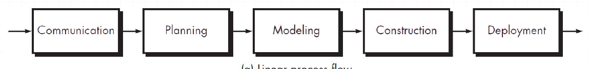
3.9.1 Linear process flow
A linear process flow executes each of the five framework activities in sequence, beginning with communication and culminating with deployment.
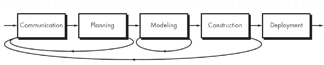
3.9.2 Iterative process flow
An iterative process flow repeats one or more of the activities before proceeding to the next activity.
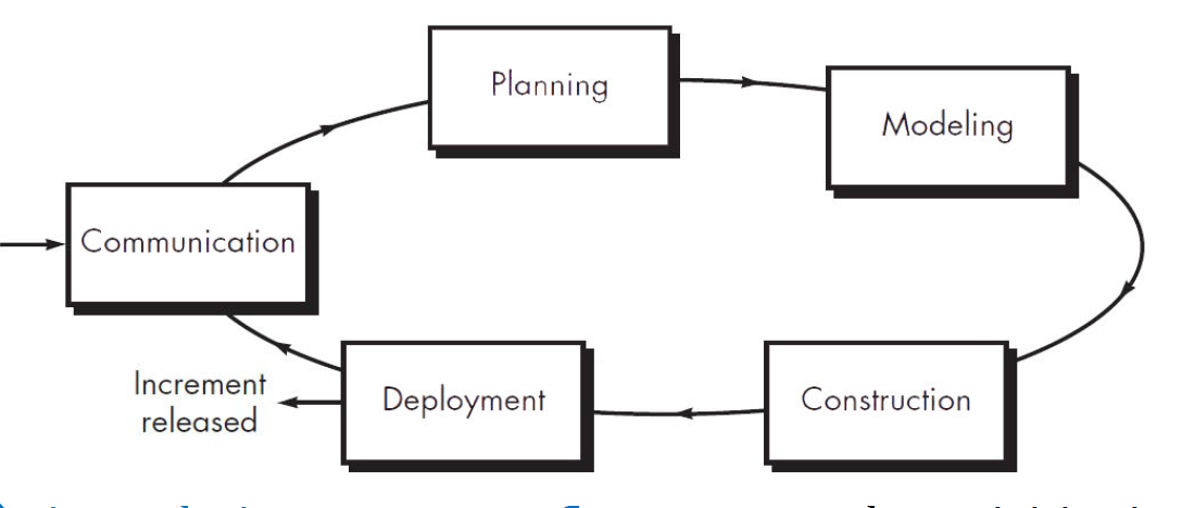
3.9.3 Evolutionary process flow
An evolutionary process flow executes the activities in a “circular” manner.
Each circuit through the five activities leads to a more complete version of the software.
3.9.4 Parallel process flow
A parallel process flow executes one or more activities in parallel with other activities.
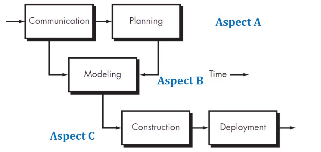
e.g., modeling for one aspect of the software might be executed in parallel with construction of another aspect of the software
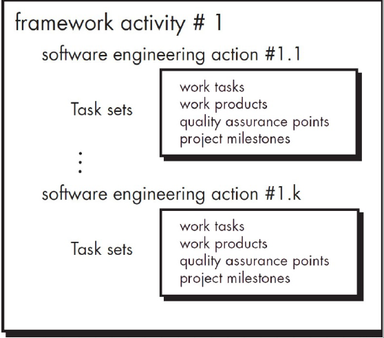
3.10 Identify a Task Set
A task set defines the actual work to be done to accomplish the objectives of a software engineering action, it includes:
- a collection of SE work tasks
- related work products
- quality assurance points
- project milestones
3.11 Process Patterns
A process pattern describes a process-related problem that is encountered during software engineering work,identifies the environment in which the problem has been encountered,suggests one or more proven solutions to the problem.
Stated in more general terms, a process pattern provides you with a template (模板)
—a consistent method for describing problem solutions within the context of the software process.
Chapter 4 Process Models
4.1 Definition of Process Model
A process model defines the flow(流程) of all activities, actions and tasks, the degree of iteration(迭代的程度), the work products, and the organization of the work that must be done.
Process model is an abstract representation of a process.Process models are not perfect, but provide a specific roadmap (steps) for software engineering work.
Software process provide stability,control, and organization to an activity that can, if left uncontrolled, become quite chaotic.
Software developers adapt a process model according to their needs and then follow it.
In practice, most large systems are developed using a process that incorporates elements from all of these models.
4.2 Prescriptive(惯用) Process Model
A prescriptive process models strives for structure and order in software development.Activities and tasks occur sequentially.
Software engineer choose process framework that includes activities like
We call this model “Prescriptive”(传统) because it prescribe(规定) a set of process elements--
--activities, actions, task, work products, quality assurance & change control mechanisms for each project.
Each process model also prescribes(定义) a process flow (called a workflow) ---that is, the manner in which the process elements are interrelated(相互关联) to one another.
4.3 Waterfall Model or Classic Life Cycle
It suggests a systematic, sequential approach to software development.Begins with customer specification of requirements and progresses through planning, modeling, construction, and deployment, culminating in ongoing support of the completed software.
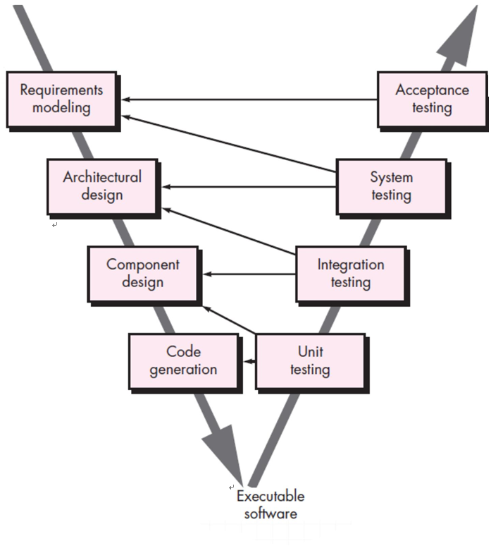
V-Model
A variation of the waterfall model
Once code generated,a series o tests quality assurance actions) are performed to validate each model created as the team moved down the left side.
In reality, there is no fundamental difference between the classic life cycle and the V-model.
Problem of the Waterfall Model
1. Real projects rarely follow the sequential model.
Changes can cause confusion as the project team proceeds.
2. It is difficult for the customer to state all the requirement explicitly.
Difficult to adapt the natural uncertainty existing at the beginning of many projects.
3. The customer must have patience.
Working version of program will not be available until late in the project time span.
A major blunder, if undetected in time, can be disastrous.
Inappropriate: software work is fas paced and subject to a never-ending stream o changes (to
features, functions, and information content).
It can serve as a useful process model in situations where requirements are fixed and work is to proceed to completion in a linear manner.
4.4 Incremental Model

Even the initial software requirements are well defined, a purely linear process is not suitable for the overall scope of development.
In addition, there may be a compelling need to provide a limited set of software functionality to users quickly and then refine and expand on that functionality in later software releases.
The incremental model combines the features of linear and parallel process flows.The incremental model applies linear sequences in a staggered fashion as calendar time progresses(biginning time are different).Each linear sequence produces deliverable “increments” of the software.
Following this model, we deliver software in small but usable pieces, each piece builds on pieces already delivered.
Rather than deliver the system as a single delivery, the development and delivery is broken down into increments with each increment delivering part of the required functionality.
First Increment is often core product
- Includes basic requirement
- Many supplementary features (known & unknown) remain undelivered.
The core product is used by the customer (or undergoes detailed evaluation).As a result of use and/or evaluation, a plan of next increment is prepared.The plan addresses the modifications of the core product.Deliver additional features and functionality.
The process is repeated following the delivery of each increment, until the complete product is produced.
It should be noted that the process flow for any increment can incorporate the prototyping paradigm.
应该注意的是,任何增量的工艺流程都可以包含原型范例。
4.5 Evolutionary Process Model
Why need Evolutionary Process Model? (3 reasons)
(1) Software evolves over a period of time. Business and product requirements often change as development proceeds.
(2)Tight market deadlines make completion of a comprehensive software product impossible, but a limited version must be introduced to meet competitive or business pressure;
(3) a set of core product requirements is well understood, but the details of product extensions have yet to be defined.
In these and similar situations, you need a process model that has been explicitly designed to accommodate a product that grows and changes.
Evolutionary Models are iterative.
It can enable you to develop increasingly more complete version of the.
Two common (常用的) Evolutionary models:
- Prototyping (原型开发)
- Spiral Model (螺旋模型)
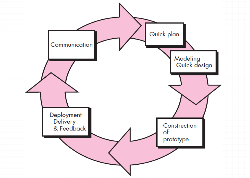
4.5.1 Prototyping
It is the best approach when:
- A customer defines general objectives but does not identify detailed requirements for functions and features.
- Developer may be unsure of the efficiency of an algorithm or the form of human machine interaction.
It can be used as standalone process model.Model assist software engineer and customer to better understand what is to be built when requirement are fuzzy.
Prototyping start with communication, between a customer and software engineer to define overall objective, identify requirements and make a boundary.软件应该和不应该提供什么功能
A prototyping iteration is planned quickly and modeling occurs.Quick design leads to prototype construction. Prototype is deployed and evaluated by the customer/user.快速策划一个原型迭代开发并建模
Iteration occurs as the prototype is tuned to satisfy the needs of various stakeholders.At the same time you can better understand what needs to be done. Prototype can be serve as a mechanism for identifying software requirements.Prototype can be serve as “the first system”.
some prototypes are built as “throwaways”(被抛弃),others slowly evolves into the actual system.
用了过时技术实现原型,因此仅用于明确需求
Both stakeholders and developers like the prototyping paradigm(原型开发范型).
- Users get a feel for the actual system
- Developers get to build something immediately.
Prototyping can be problematic because outdate techniques or inefficient algorithms were used to implement it.
开发者熟悉,可快速实现
The key is that we should define the rules at the beginning :
- all stakeholders should agree that the prototype is built to serve as a mechanism for defining requirements.
- It is then discarded 丢弃 (at least in part), and the actual software is engineered with an eye toward quality.
以质量为第一目标而开发的
4.5.2 Spiral Model
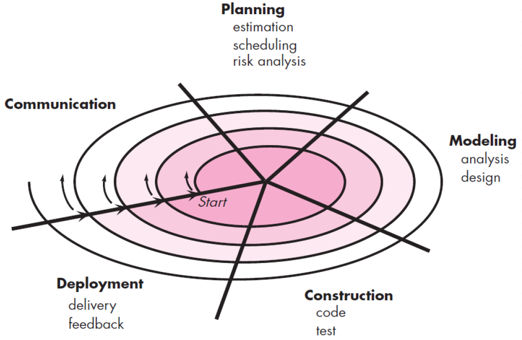
The spiral model is an evolutionary software process model.**It couples iterative nature of prototyping with the controlled and systematic aspects of th waterfall mode .**It provide potential for rapid development of increasingly more complete version of the software.
Using spiral model, software developed in as series of evolutionary release.
- During early iterations, the release might be on paper or prototype.
- During later iterations, more complete version (完整版本) of software.
Each segment of the spiral path represents one of the framework activities.Each iteration is one circuit around the spiral, going through from communication to deployment.
Evolutionary process performs activities that are implied by a circuit around the spiral in a clockwise direction beginning at the center.First circuit around the spiral might result in
development of product specification.Subsequently, develop prototype and then progressively mor sophisticated version of software.
Spiral Model has two main distinguishing features:
(1) Risk is considered as each evolution is made.
(2) Anchor point milestones are noted for each evolutionary pass--—the work products produced in each iteration / evolution.
Unlike other process models that end when software is delivered, it can be adapted to apply throughout the life of software.The great difference between Spiral Model and the rest models lies in that Spiral Model considers the risk as each evolution is made(during each iteration).
Spiral models uses prototyping as a risk reduction mechanism but, more important, enables the developer to apply the prototyping approach at any stage in the evolution of the product.It maintains the systematic stepwise approach suggested by the classic life cycle but incorporates it into an iterative framework.
Problem Area:
It may be difficult to convince customers (particularly in contract situations) that the evolutionary approach is controllable.If a major risk is not uncovered and managed,problems will undoubtedly occur.
4.6 Differences between Incremental Model and Spiral Process
- (1) Iteration levels are different.
IM iterates activities, but SP iterates processes. - (2) The time when making requirements analysis are different.
IM often makes overall requirements analysis and conceptual design first, then do incremental detailed design, coding and testing one by one function point (module),but SP makes requirements analysis using waterfall model or prototyping paradigm during each iteration period. - (3) The ways of delivery are different.
IM delivers a new part of software based on the previous increment,but SP delivers a new and complete software version at the end of each iteration.
4.7 Specialized Process Models
Specialized Process Models take on many of the characteristics of one or more of the traditional models.However, these models tend to be applied when a specialized or narrowly defined software engineering approach is chosen.
Component-Based Development
Component-based development (CBD) model incorporates many of the characteristics of the spiral model.It is evolutionary by nature and iterative approach to create software.CBD model creates applications from prepackaged software components (called classes).
Software Component (i.e. module,class,package)is like toy bricks (积木). CBD Model assemble(组装) some available and reusable components to build a complete software system.
Modeling and construction activities begin with identification of candidate components. CBD model leads to software reuse.
Components reuse will result in a reduction in development cycle time and project cost.
- Based on studies, CBD model leads to 70 % reduction in development cycle time.
- 84% reduction in project cost.
- Productivity is very high.
Chapter 7 Understanding Requirements
7.1 Concepts about Requirements Engineering
• Requirement: A function, constraint or other property that the system must provide to fill the needs of the system’s intended user(s).
• Requirement Engineering means that requirements for a product are defined, managed and tested systematically.
• The broad spectrum(范围) of tasks and techniques that lead to an understanding of requirements is called Requirement Engineering .
• It is essential that the software engineering team understand the requirements of a problem before the team tries to solve the problem.
•RE is software engineering actions tha start with communication activity and continues into the modeling activity.(plan)
• RE establishes a solid base for design and construction. Without it, resulting software has a high probability of not meeting customer needs.
7.2 Two types of requirements
Functional requirements(功能需求) describe
- the functionality or service that the system should provide
- how the system should react to particular inputs,
- how the system should behave in particular situations.
- In some cases, the functional requirements may also explicitly state what the system should not do.(boundary)
Nonfunctional requirements (非功能需求) describe the constraints on the services or functions offered by the system,such as reliability (可靠性), response time(响应时间), store occupancy (存储空间的占用) and maintainability(可维 护性), or relate to the environment in which the software will run.It often apply to the system as a whole rather than individual features or services.
7.2.1 Founctional requirements
Describe functionality or system services.Depend on the type of software, expected users (潜在用户) and the type of system where the software is used.Functional requirements should describe the system services in detail.Problems will arise when requirements are not precisely (精确地)stated.Ambiguous (有歧义的)requirements may be interpreted (理解)in different ways by developers and users.It is natural for a system developer to interpret an ambiguous requirement in a way that simplifies its implementation.Often, however, this is not what the customer wants.(开发者怎么简单怎么做,客户当然不愿意)
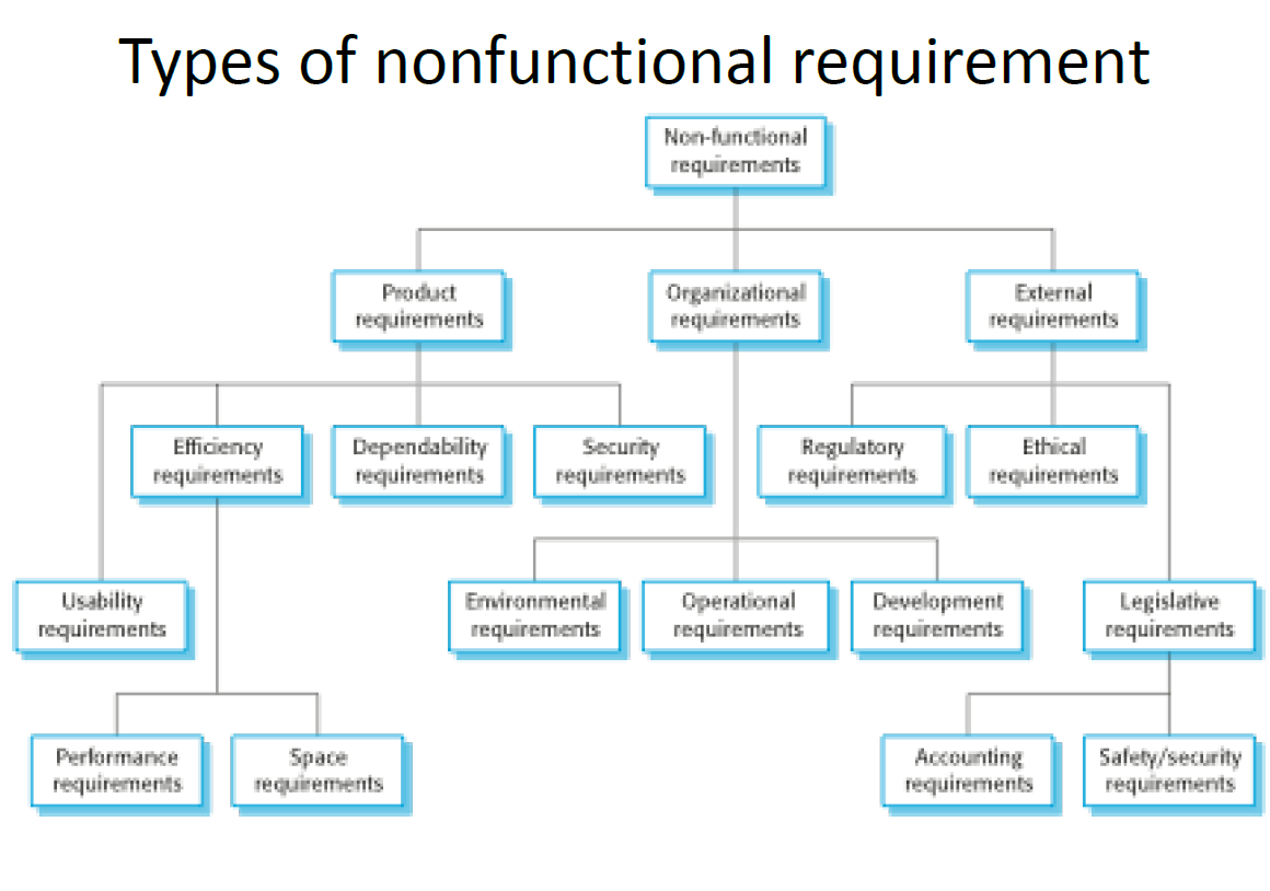
7.2.2 Non-functional requirements
They are requirements that are not directly concerned with the specific services delivered by the system to its users.They may relate to emergent system properties such as reliability, response time, and store occupancy.Alternatively, they may define constraints on the system implementation such as the capabilities of I/O devices or the data representations used in interfaces with other systems.
Non-functional requirements may be more critical than functional requirements. If these are not met, the system may be useless.For example, if an aircraft system does not meet its reliability (可靠性) requirements, it will not be certified as safe for operation(不会被批准飞行);if a real-time control system fails to meet its performance requirements, e.g. response time, the control functions will not operate correctly.
Non-functional requirements may be very difficult to state precisely , and imprecise requirements may be difficult to verify .
How to verify non-functional requirement and judge whether they meet the stakeholders’ needs?
Whenever possible, you should write non-functional requirements quantitatively so that they can be objectively tested.
For example, the following system goal is typical of how a manager might express usability (可用性) requirements:.
The system should be easy to use by medical staff and should be organized in such a way that user errors are minimized.It is impossible to objectively verify the above goal, but in
the description below you can at least count the errors made by users when they are testing the system. Medical staff shall be able to use all the system functions after four hours of training. After this training, the average number of errors made by experienced users shall not exceed two per hour of system use.
Metrics (度量)for specifying nonfunctional requirements
| Property | Measure |
|---|---|
| Speed | Processed transactions/second, User/event response time Screen refresh time |
| Size | Mbytes, Number of ROM chips |
| Ease of use | Training time, Number of help frames |
| Reliability | Mean time to, failure Probability of unavailability, Rate of failure occurrence, Availability |
| Robustness(鲁棒性) | Time to restart after failure, Percentage of events causing failure,Probability of data corruption on failure |
| Portability | Percentage of target dependent statements, Number of target systems |
7.2.3 Requirement completeness and consistency
In principle, requirements specification should be both complete and consistent.
Complete(完备)
Completeness means that all services required by the user should be defined.
Consistent(一致)
Consistency means that requirements should not have contradictory (矛盾的) definitions.
In practice, for large, complex systems, it is impossible to produce a complete and consistent requirements document. Because it is easy to make mistakes and omissions(遗漏,疏忽)when writing specifications for complex systems.
There are many stakeholders (利益相关者,干系人).Stakeholders have different—and often inconsistent needs. These inconsistencies may not be obvious when the requirements are first specified, so inconsistent requirements are included in the specification. The problems may only emerge after deeper analysis or after the system has been delivered to the customer.
7.3 Characteristics of a Good Requirement
Besides Complete and Consistent, it should have the following 5 features:
Clear and unambiguous
- Invent a standard format (标准的书写格式)and ensure that all requirement definitions adhere to that format. Standardizing the format makes omissions less likely and requirements easier to check.
- Express the requirement in a single sentence
- Define standard specification structure –templates
- Has only one possible interpretation
Correct
Verifiable(可验证的)
Traceable(可追踪的)
7.4 Requirements Engineering Tasks
- Inceptio (起始): establish a basic understanding of the problem and the nature of the solution.
- Elicitatio (获取): collect requirements from all stakeholders.
- Elaboration (细化Highly structured): create an analysis model that identifies data, function and behavioral requirements.
- Negotiatio (协商): agree on a deliverable system that is realistic for developers and customers.
- Specificatio (规格说明): describe the requirements formally or informally.
- Validatio (确认): review the requirement specification for errors, ambiguities, omissions, and conflicts.
- Requirements managemen (需求管理): manage changing requirements.
7.4.1 Inceptio
Inception—start-up(启动), is to initiate RE Process.
The steps of inception is as follows:
- Identif stakeholders
- Recognize multiple points of view
- Working toward collaboration
- Asking the first questions
7.4.1.1 Identify stakeholders
Stakeholder can be “anyone who benefits in a direct or indirect way from the system which is being developed”,E.g., Business manager, project manager, marketing people, software engineer, support engineer, end-users, consultants, maintenance engineer.Each one of them has different view of the system.
7.4.1.2 Recognize multiple points of view
Views from different stakeholder :
- Marketing group – concern about features and functions to excite potential market. To sell easily in the market.
- Business manager – concern about features built within budget and will be ready to meet market.
- End user – Easy to learn and use.
- Software Engineer –concern with functions invisible to non-technical stakeholders but enable infrastructure to support more marketable functions and features.
- Support engineer – Maintainability of software.
Each of these participants will contribute information to the requirements engineering process.As information from multiple viewpoints is collected, emerging requirements may be inconsistent or may conflict with one another.The job of Requirement Engineers is to categorize all stakeholder information in a way that there could be no inconsistent or conf lict requirement with one another.
7.4.1.3 Working toward collaboration
The job of a requirements engineer is to identifies areas of commonality (i.e. agreed requirement) and areas of conflict or inconsistency.Collaboration does not mean requirement defined by committee. Stakeholders provide their view of requirements.A strong “project champion” (e.g. a business manager or senior technologist) may make final decision about which requirements should be cut.
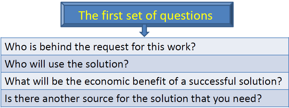
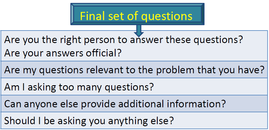
7.4.1.4 Asking the first questions
These questions will help to identify
• stakeholders who have interest in the software
• measurable benefit of successful implementation
It helps to Better understanding of the problem
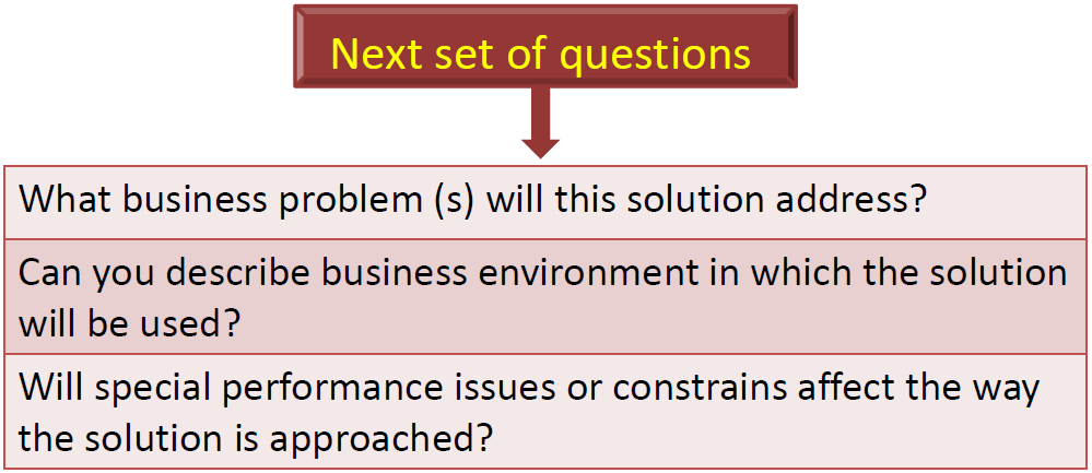
It focuses on the effectiveness of communication activity itself.
7.4.2 Elicitiation
Elicitation – elicit requirements from customers, users and others.Sometimes called requirements elicitation or requirements gathering (collection).
People Involved: end-users, customers(clients), managers, engineers, domain experts, etc. These are called stakeholders. Systems normally have a range of stakeholders.
Questions focusing on:
What the objectives for the system or product are? What is to be accomplished?
How the system or product fits into the needs of the business?
How the system or product is to be used on a day-to day work?
Tasks of Elicitation Requirement
To find out the following questions:
- application domain
- the services that the system should provide – the system’s operational constraints
- the required system performance – hardware constraints
- …..
Why Requirement Elicitation Is Difficult?
Problems of scope:
- The boundary of the system is ill-defined.
- Customers/users specify unnecessary technical detail that may confuse rather than clarify objectives.
Problems of volatility :反复无常
- Requirement change over time.
Problems of understanding:
- Customers are not completely sure of what is needed.
- Customers have a poor understanding of the capabilities and limitations of the computing
environment.(message/calling) - Customers don’t have a full understanding of their problem domain.
- Customers have trouble in communicating needs to the system engineer.
- Customers omit detail that is believed to be obvious.
- Customers specify requirements that conflict with other requirements.
- Customers specify requirements that are ambiguous or not able to test.
Steps for eliciting requirement:
- Collaborative Requirement Gathering
- Quality Function Deployment
- Usage Scenarios
- Elicitation Work Products
7.4.2.1 Collaborative Requirement Gathering
Many different approaches to collaborative requirements gathering have been proposed as following.
- Meetings are attended by all interested stakeholders.
- Rules are established for preparation and participation.
- Agenda should be formal enough to cover all important points, but informal enough to encourage the free flow of ideas.
- A facilitator (developer, customer, others)controls the meeting.
- A definition mechanism (work sheets, flip charts, wall stickers, electronic bulletin board, chat room, virtual forum) is used.
- During the meeting:
- The problem is identified.
- Elements of the solution are proposed.
- Different approaches are negotiated.商讨
- A preliminary set (初步集合)of solution requirements are obtained.
- The atmosphere is collaborative and non-threatening.
Now each sub-team makes a list of validation criteria for the product and present to team.
Finally, one or more participants is assigned the task of writing a complete draft specification.
7.4.2.2 Quality Function Deployment
QFD is a technique that translate the needs of the customer into technical requirement for software.
The goal of QFD is to concentrate on maximizing customer satisfaction.
QFD emphasizes – what is valuable to the customer and then deploys these values throughout the engineering process.
Three types of requirements:
Normal Requirement 常规)
identify objectives and goals that are stated for product. If requirements are present , the customer is satisfied.
Expected Requirement 期望)
customer does not explicitly state them. Customer assumes it is implicitly available (隐含可获得)with the system. Their absence will be a cause for significant dissatifaction.
Exciting Requirement 兴奋
go beyond (超出) the customer ’s expectation and prove to be very satisfying when present.
How to achieve the goal of QFD?
QFD uses customer interviews and observation, surveys, and examination of historical data (e.g., problem reports) as raw data for the requirements gathering activity.
These data are then translated into a table of requirements—called the customer voice table —that is reviewed by the customer and other stakeholders.
A variety of diagrams, matrices, and evaluation methods are then used to extract expected requirements and to attempt to derive exciting requirements.
7.4.2.3 Usage Scenario
It is difficult to move into more technical software engineering activities until software team understands how these functions and features will be used by different end-users.
The scenarios , often called **use-cases provide a description of how the system will be used.
Use cases
A use-case tells a stylized story about how an end user (known as an actor) interacts with the system.
A user case depicts the software or system from the end user's point of view.
The first step in writing a use case is to define the set of “actors” that will be involved in the story.
Actors
Actors are the different people(or devices ) that use the system within the context of the function and the behavior.
More formal definition for an actor: It is anything that communicates with the system and that is external to the system itself.Actors are not part of the system ----EXTERNAL
Actors can represent a human, a machine, or another system that plays with the system.
What is Actor for?
Actors help (界定) the system and give a clearer picture of what it is supposed to do.
Use cases are developed on the basis of the actor ’s needs, ensuring that the system turns
out to be what the users expected.
User and Actor
An actor and a user are not the same thing.
A user can play a number of different roles when using a system, whereas an actor represents a class of external entities (often, but not always, people) that play just one role.
Actor is represented as stickman named by singular domain-related noun, which can reflect the role that one plays in the model precisely.
参与者用一个小人来代表,这个小人要用一个单数的、与领域相关的名词来命名。这个名词应该能够准确地反应出,用户与模型进行交互时,所扮演的角色。
They can be a giver of information, or a passive recipient of information.
参与者可能是信息的主动给予者,也可能是信息的被动接收者。
The name of use-case begin with a strong verb.
The relationships between Actors
Generalization(泛化)
- Sub-actor inherits super-actor's actions
- Sub-actor can also have its own actions
Agency
Dotted line directs from agency(requestor to agency)
从代理请求者用虚线指向代理
The relationship between use cases
Inclusion
Extension
扩展点(被扩展用例某一结果)
7.4.2.4 Elicitation Work Products
Elicitation work product will vary depending upon the size of the system or product to be built.
The work products include:
①A statement of need and feasibility.
②A bounded statement of scope for the system or product.
③a list of customers, users, and other stakeholders who participated in requirements elicitation.
④ Description of the system’s technical environment.
⑤ A list of requirements (preferably organized by function) and the domain constraints that apply to each.
⑥ A set of usage scenarios that provide insight into the use of the system or product under different operating conditions.
⑦ Any prototypes developed to better define requirements.
7.4.3 Elaboration
This task focuses on developing a refined requirements model that identifies software functions behavior, and information obtained during inception and elicitation.
It is driven by the creation and refinement of user scenarios that describe how the end-user (and other actors) will interact with the system.
Elaboration— create an analysis model that identifie data,function and behavioral requirements.
7.4.4 Negotiation
Negotiation - agree on a deliverable system that is realistic for developers and customers.
Given limited business resources, it is usual for customers and users to ask for more than can be achieved.It ’s also relatively common for different customers or users to propose conflicting requirements, arguing that their version is “ essential for our special needs”.You have to reconcile these conflicts through a process of negotiation.
How to solve these conflicts
- Ask stakeholders to ranked (排序) their requirements and then discuss conflicts in priority .
- Assesses the cost and risk of requirements, addresses internal conflicts.
- Requirements are eliminated, combined and/or modified so that each party achieves some measure of satisfaction.
- There should be no winner and no loser in effective negotiation. (need to compromise )
7.4.5 Specification
A software requirement specification (SRS)is a work product that is created when a detailed description of all aspects of the software to be built must be specified before the project is to commence.
It is important to note that a formal SRS is not always written.In fact, there are many instances in which effort expended (花费) on an SRS was less than that on other software engineering activities.However, when software is to be developed by a third party, when a lack of specification would create severe business issues, or when a system is extremely complex or business critical, an SRS may be justified.
Specification means different things to different people. It can be
- Written document
- A set of graphical models
- A formal mathematical model
- A collection of usage scenario
- A prototype
- Combination of above
The formality and format of a specification varies with the size and the complexity of the software to be built.For large systems, written document, language descriptions,and graphical models may be the best approach.For small systems or products, usage scenarios are enough.
SRS contains
- a complete information description
- a detailed functional description
- a representation of system behavior
- an indication of performance requirements and design constraints
- appropriate validation criteria
- other information pertinent to requirements
Format of SRS
Introduction
It states the goals and objectives of the software, describing it in the context of the computer-based system.
Information Description
It provides a detailed description of the problem that the software must solve.
- Information content, flow, and structure are documented.
- Hardware, software, and human interfaces are described for external system elements and internal software functions.
Functional Description
- A processing narrative is provided for each function.
- Design constraints are stated and justified.
- Performance characteristics are stated.
Behavioral Description
section of the specification describes the operation consequence of the software when an external events occurs.
Validation Criteria
It is probably the most important and, ironically, the most often neglected section of the SRS. Testing or validating each user-scenario.
Bibliography and Appendix.
- The bibliography contains references to all documents that relate to the software.
- The appendix contains information that supplements the specification.
7.4.6 Validation
During a validation step,the work products produced as a consequence of requirements engineering are assessed for quality.
It examines the requirement specification to ensure
- all software requirements have been stated unambiguously;
- inconsistencies, omissions, and errors have been detected and corrected;
- the work products conform to the standards established for the process, the project, and the product.
The primary requirements validation mechanism is the technical review .
A review of the SRS is conducted by the review team including both software developers and customers.First, the review team conducts examination for specification at a macroscopic level, looking for
– Errors in content or interpretation
– Areas where clarification may be required
– Missing information
– Inconsistencies ( a major problem when large products or systems are engineered)
– Conflicting or unrealistic (unachievable) requirements.
Then review becomes more detailed while examining Information, functional and behavioral domain.
Review team Examines not only the broad descriptions but also the way in which requirement worded.E.g. Terms like “Vague ” (some, sometimes, often, usually) should be quantified (量化) or give further clarification .Once review is complete – SRS is “signed off” by both customer and developer. ( “contract” for software development)
Requests for changes in requirements after the specification is finalized will not be eliminated.
Change is an extension of software scope and therefore can increase cost.
Requirements Validation Checklist
Questions are asked and answered to ensure that the requirements model is an accurate reflection of stakeholder needs and that it provides a solid foundation for design.
– Are requirement stated clearly? Can they be misinterpreted?
– Is the source (person, document) of the requirements identified? Has the final statements of the requirement been examined by or against the original source?
– Is the requirement bounded in quantitative terms?
– What other requirements relate to this requirement? Are they clearly noted via across-reference matrix or other mechanism?
– Does the requirements violate any system domain constraints?
– Is the requirement testable? If so, can we specify tests (validation criteria)to exercise the requirement?)?
– Is the requirement traceable to any system model that has been created?
– Is the requirement traceable to overall system/product objectives?
– Is the specification structured in a way that leads to easy understanding, easy refernce, and easy translation into more technical work products?
– Has an index for the specification been created?
– Have requiremtns associated with performance, behavior, and operational characteristics been clearly stated? what requirements appear to be implicit?
7.4.7 Requirement Management
Requirements for computer-based systems may change, and the desire to change requirements persists throughout the life of the system.
- Requirements management is the process of managing changing requirements during the requirements engineering process and system development.
- Requirements management is a set of activities that help project team to identify, control, and track requirements and changes as project proceeds.
- New requirements emerge as a system is being developed and after it has gone into use.
- You need to keep track of individual requirements and maintain links between dependent requirements so that you can assess the impact of requirements changes.
- You need to establish a formal process for making change proposals and linking these to system requirements.
Chapter 8 Requirements Modeling: Scenario Methods
At a technical level, software engineering begins with a series of modeling tasks(建模任务) that lead to a specification of requirements and a design representation for the software to be built.
The requirements model (analysis model)— actually a set of models—is the first technical representation of a system.
8.1 Requirements Analysis
Requirements analysis
- results in the specification of software’s operational(操作) characteristics,
- indicates software‘s interface with other system elements,
- establishes constraints that software must meet.
Requirements analysis is conducted by a software engineer, an analyst, or a modeler.The software analyst (or modeler ) elaborates on basic requirements established during the inception, elicitation, and negotiation tasks.
8.2 Requirements Modeling
Requirements Modeling is the process of building Requirements Models, with each model presenting a different view or perspective of that system.Requirements Modeling is also called or Analysis Modeling.Analysis modelling helps the analyst to understand the functionality of the system, and models are used to communicate with customers.
Requirements Modeling uses a combination of text and diagrammatic forms to depict(描述) requirements in a way that is relatively easy to understand, and more important, straightforward to review for correctness, completeness ,and consistency.
8.3 Requirements Models
The Requirements Modeling action results in one or more of the following types of diagrammatic models (图模型).
- user scenarios, Scenario-based models of requirements from the point of view of various system “actors”.
- Class-oriented models that represent object-oriented classes (attributes and operations) and the manner in which classes collaborate to achieve system requirements.
- Behavioral and pattern-based models that depict how the software behaves as a consequence of external ”events”.
These models provide a software designer with information that can be translated to architectural-, interface-, and component-level designs.(从粗到细,从整体到模块)
Analysis model and the requirements specification provide the developer and the customer with the means (手段)to assess quality once software is built. (在软件设计与实现阶段有用,在测试阶段依然有用)
8.4 Overall Objectives and Philosophy
Throughout analysis modeling, the software engineers’ primary focus is on what,not on how.
- What user interaction occurs in a particular circumstance?
- What objects does the system manipulate(处理)?
- what functions must the system perform?
- what behaviors does the system exhibit(展示)?
- what interfaces are defined?
- what constraints apply?
The requirements model must achieve the following three Primary Objectives:
- To describe what the customer requires.
- To establish a basis for the creation of a software design.
To define a set of requirements that can be validated once the software is built(coded, not delivered).
System description describes overall system or business.
Design model describes the software’s application architecture, user interface, and component-level structure.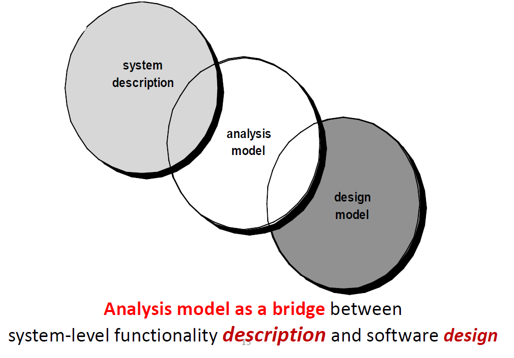
分析模型的抽象级别比设计模型的抽象级别高,意味着细节少
8.5 Analysis Rules of Thumb
Experts suggest a number of worthwhile rules of thumb that should be followed when creating the analysis model:
1. The model should focus on requirements that are visible within the problem or business domain. The level of abstraction should be relatively high. – Don’t get bogged into the details.
2. Each element of the analysis model should add to an overall understanding of software requirements and provide insight into the information domain, function and behavior of the system.
3. Delay consideration of infrastructure(基础结构) and other non-functional models until design.
e.g., Database design should be considered only after problem domain analysis has been completed.
4. Minimize coupling throughout the system.
- If level of interconnectedness is high, efforts should be made to reduce it.
5. Be certain that the analysis model provides value to all stakeholders.
– Business stakeholders should validate requirement;
– Designers should use the model as a basis for design;
– QA people should use the model to help plan acceptance tests.
6. Keep the model as simple as it can be.
- No need to add additional diagrams when no new information, and no need to use complex notations forms when a simple list will do.
8.6 Domain Analysis and Analysis Pattern
Anyone who has done requirements engineering on many software projects begins to notice that certain problems reoccur across all projects within a specific application domain.
These analysis patterns suggest solutions (e.g., a class, a function, a behavior) within the application domain that can be reused when modeling many applications.
If you want to obtain solutions to customer requirements more rapidly and provide your team with proven approaches, use analysis patterns.
There are two benefits of using analysis patterns.
- First, analysis patterns speed up the development of building analysis models, it can quickly capture the main requirements of the concrete problem by providing reusable analysis models.
Second, analysis patterns facilitate the transformation of the analysis model into a design model by suggesting design patterns and reliable solutions for common problems.
But how are analysis patterns and classes recognized in the first place?Who defines them, categorizes them, and readies them for use on subsequent projects?The answers to these questions lie in domain analysi .
Software domain analysis is the identification,analysis, and specification of common requirements from a specific application domain, typically for reuse on multiple projects within that application domain .
Objec oriented domain analysis is the identification, analysis, and specification of common, reusable capabilities within a specific application domain, in terms of common objects, classes, subassemblies, and frameworks .
The goal of domain analysis is straightforward: to find or create those analysis classes and/or analysis patterns that are broadly applicable so that they may be reused.Domain analysis may be viewed as an umbrella activity for the software process.
8.7 Domain Analyst (域分析师)
The role of a domain analyst is similar to the role of a master toolsmith in a heavy manufacturing environment. 类似于重型机械制造业中一名优秀的刀具工。The job of the toolsmith is to design and build tools that may be used by many people doing similar but not necessarily the same jobs.The role of the domain analyst is to discover and define analysis patterns, analysis classes, and related information that may be used by many people working on similar but not necessarily the same applications. 用于类似但不必完全相同的应用中。
8.8 Requirements Modeling Approaches
There are two approaches.
- Structured Analysis(结构化分析):
Data objects are modeled in a way that defines their attributes (属性)and relationships(联系).
Processes that manipulate (处理)data objects are modeled in a manner that shows how they transform data as data objects flow through the systems.
考虑数据和将数据当做单独的实体进行转化的过程 - Object-Oriented Analysis :
Focuses on the definition of classes and the manner in which they collaborate with one another.
UML is predominantly object oriented.
关注类的定义,并关注影响客户需求的类之间的协作方式
8.9 Graphical Modeling Languages
Graphics should be used whenever possible because it is easy for users and designers to understand and communicate.
Analysis modeling has come to mean representing a system using some kind of graphical notation, which is now almost always based on notations in the Unified Modeling Language (UML).In many cases, there is no need to create a graphical representation of a usage scenario.However, diagrammatic representation can help understanding, particularly when the scenario is complex.
Types of UML diagrams
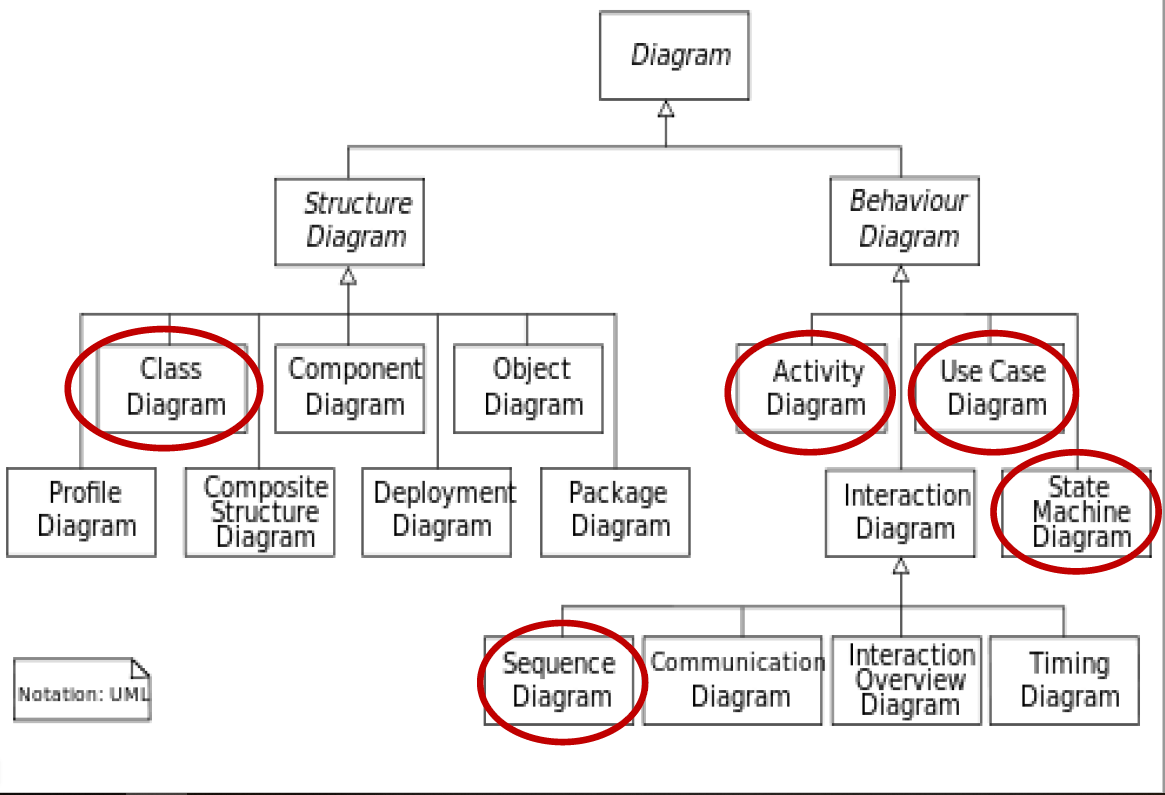
8.10 Three types of Modeling Method
- Scenario-Based Modeling 基于场景的建模
- Use-case Models / Use-case Diagram 用例图
- Class-based Modeling 基于类的建模
- Class Diagram 类图
- Class-responsibility-collaborator (CRC) model 类-职责-协作者模型
- Behavioral Modeling 行为建模
- Activity diagrams 活动图
- State Diagram 状态图
- Sequence Diagram 时序图/ 顺序图
8.10.1 Scenario-Based Modeling
Use-case Models(用例模型)
Depict how the user interacts with the system, and the specific sequence of activities that occur as the software is used.
Use-case diagrams (用例图)
Use-case Models are represented by Use-case diagrams. They show the interactions between a system and its users.
8.10.2 Class-Based Modeling
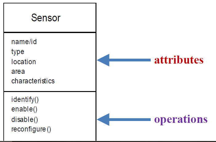
Class Diagrams model the objects that the system will manipulate, the operations that will be applied to the objects to effect the manipulation, relationships (some hierarchical) between the objects and the collaborations that occur between the classes that are defined.
In a single word, Class diagrams show the object classes in the system and the associations between these classes.
Each usage scenario implies a set of objects that are manipulated as an actor interacts with the system.These objects are categorized into classes—a collection of things that have similar attributes and common behaviors.
For example, a UML class diagram can be used to depict a Sensor class for the SafeHome security.
Note that the diagram lists the attributes of sensors (e.g., name, type) and the operations (e.g., identify, enable ) that can be applied to modify these attributes.
8.10.3 Behavioral Modeling
Behavioral models Depict how the external events change the state of the system or the classes that reside within it.
Activity diagrams
which show the activities involved in a process or in data processing .
Sequence diagrams
which show interactions between actors and the system and between system components.
State diagrams
which show how the system reacts to internal and external events.
8.11 Scenario-Based Modeling
A use case describes a specific usage scenario in straightforward language from the point of view of a defined actor.
Use-Case Model
It describes a system’s functional requirements in terms of use cases, which may consists of several use cases. Use-case Models are represented by Use-case diagrams.
Use-Cases Diagram
Us case diagram are simply to define what exists outside the system (actor) and what should be
performed by the system (use-case).A use case is represented as ellipse with case name inside, which is domain-related and starts with strong verb.
So a Use-Case diagram includes 3 elements:
- actors----System’s role
- use cases ---- System’s intended functions
- Relationship between actors and use-cases
Generalization、Agency、Inclusion、Extension
Association between Actors and Use Cases
- A use case is initiated by an actor to invoke a certain functionality in the system.
- A use case simulates a dialogue between one or more actors and the system.
Association Symbol
An actor is connected to one or more use cases, by an association, which is represented as a line
between the actor and the use cases.An association between an actor and a use case indicates that the actor and the use case communicate with one another, each one able to send and receive messages.
The steps of Scenario-Based Modeling
1. Creating a Preliminary Use Case
2. Refining a Preliminary Use Case
3. Writing a Formal Use Case
8.11.1 Creating a Preliminary Use Case
But the following questions must be answered.
(1) What should we write about? 编写什么?
(2) How much should we write about it? 写多少?
(3) How detailed should we make our description?写多详细?
(4) How should we organize the description?如何组织描述?
8.11.1.1 What should we write about?
Analyze the information that you collected during the stages of Inception and elicitation.
Requirements gathering meetings, Quality Function Deployment, and other requirements engineering mechanisms are used to
- identify stakeholders (确定干系人)
- define the scope of the problem (定义问题范围)
- specify overall operational goals(说明整体的运行目标)
- establish priorities (建立需求的优先级顺序)
- outline all known functional requirements (概述功能需求)
- describe the things (objects) that will be manipulated by the system. 描述系统将处理的信息(对象)
To begin developing a set of use cases, list the functions or activities performed by a specific actor.
8.11.1.2 How Much to Write About?
As further conversations with the stakeholders progress, the requirements gathering team develops
use cases for each of the functions noted.It should describe all functions required by the users.
8.11.1.3 How detailed should we make our description?/How should we organize the description?
In general, use cases are written first in an informal narrative fashion.If more formality is required, the same use case is rewritten using a structured format.
In many cases, there is no need to create a graphical representation of a usage scenario.However, diagrammatic representation can help understanding, particularly when the scenario is complex.UML does provide use case diagramming capability.Besides description in text for use-cases, sometimes use-cases diagrams are necessary.
8.11.2 Refining a Preliminary Use Case
A description of alternative interactions is essential for a complete understanding of the function that is being described by a use case.Therefore, each step in the primary scenario is evaluated by asking the following questions:
- Can the actor take some other action at this point?
- Is it possible that the actor will encounter some error condition at this point? If so, what might it be?
- Is it possible that the actor will encounter some other behavior at this point (e.g., behavior that is invoked by some event outside the actor ’s control)? If so, what might it be?
Answers to these questions result in the creation of a set of secondary scenarios that are part of the original use case but represent alternative behavior.
8.12 Use Case Diagram
There are many requirements modeling situations in which a text-based model may not impart(传递) information in a clear and concise manner.In such cases, you can choose from a broad array
of UML graphical models.
8.13 Conclusion for Scenario-Based Modeling
- Use case diagrams is used to depict how external actors interact with the system
- Use case focuses on the functional and operational requirements , not nonfunctional. (functionality)
- But Use case diagrams can not depict how software functions are processed in the system (behavior details)
- Behavior can be represented at many different level of abstraction, e.g., flow charts; activity diagrams (Behavioral Models).
8.14 Behavioral Mode - activity diagram
So UM activity diagram supplements the use case by providing a graphical representation of the flow of interaction within a specific scenario.
It may be used to define business process models.
- Rounded rectangles are used to imply a specific system function .
- Arrows are used to represent flow through the system.
- Decision diamonds(菱形) are used to depict a branching decision (each arrow emanating from the diamond is labeled).
- activity diagram adds additional detail not directly mentioned(but implied) by the use case.
E.g. A user may only attempt to enter userID and PassWord a limited number of times.This is represented by a decision diamond of “prompt for reentry ”
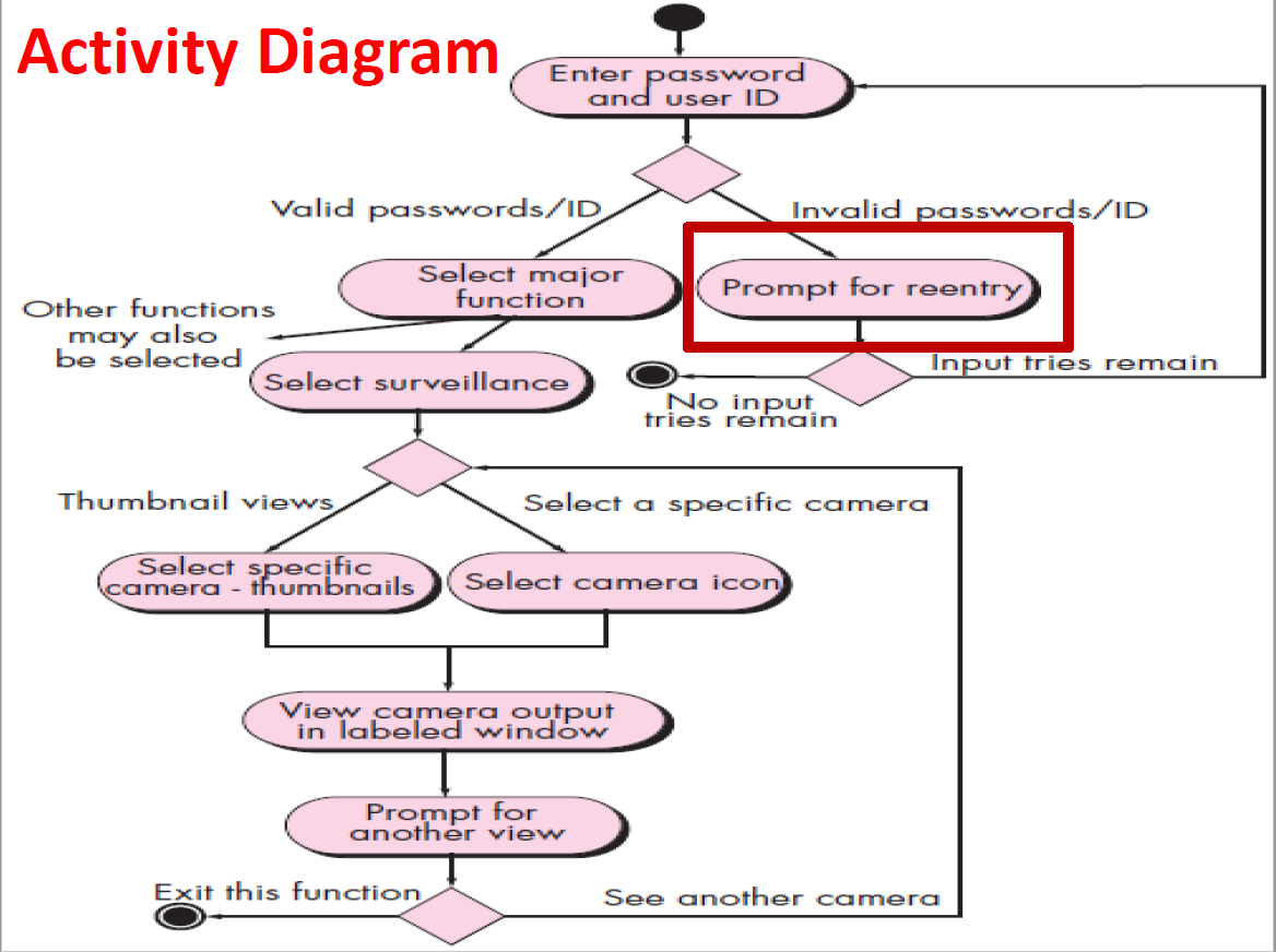
8.15 Behavioral Models--Swimlane Diagrams
The UM swimlane diagram is a useful variation of activity diagram.
It allows the modeler to represent the flow of activities described by the use-case and indicate which actor or analysis class has responsibility for the action described by an activity rectangle.Responsibilities are represented as parallel segments that divide the diagram vertically, like the lanes in a swimming pool.
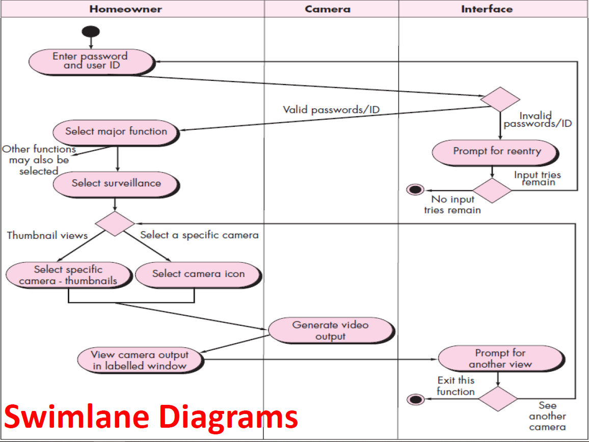
Chapter 9 Class-based Modeling
Class-based modeling represents:
- objects that the system will manipulate
- operations (also called methods or services) that will be applied to the objects to effect the manipulation
- relationships (some hierarchical) between the objects
- collaborations that occur between the classes
The result of class-based modeling is class diagram (类图).
9.1 What is a class diagram?
A class diagram shows the existence of entity classes and their relationships in a software system.
Class diagrams show the static structure of the model, in particular, the things that exist such as classes, their internal structure (attributes), and their relationships to other classes.It is the static view of a system, primarily supports the functional requirements of a system.
9.2 Two Approaches to Class Modeling
Noun extraction
Always works
CRC, Class-Responsibility-Collaboration
CRC卡片方法
- Need to have domain expertise
- More suitable for testing class diagram
9.3 Class-based Modeling
The steps of Noun Extraction modeling is:
• Identifying analysis classes
• Specifying attributes
• Defining operations
9.3.1 Identifying analysis classes
Examining the usage scenarios developed as part of the requirements model and perform a "grammatical parse"对用例进行语法分析
- Classes are determined by underlining each noun or noun phrase and entering it into a simple table.
- Synonyms should be noted.标注同义词
But what should we look for once all of the nouns have been isolated?
Analysis classes manifest(表现) themselves in one of the following ways:
1. External entities that produce or consume information
– other system, people, devices, …
2. Things that are part of the information domain for the problem.
– reports, displays, letters, signals, …
3. Occurrences or events that occur within the context of system operations.
– a property transfer所有权
– the completion of a series of robot movements…
4. Roles played by people who interact with the system.
– manager, engineer, salesperson, …
5. Organizational units that are relevant to an application.
– Division, group, team, …
6. Places that establish the context of the problem and overall function of the system.
– manufacturing floor, loading dock …
7. Structures that define a class of objects or related classes of objects. sensors, four-wheeled vehicles, computers, …
9.3.2 Specifying Attributes
Attributes describe a class that has been selected for inclusion in the analysis model.
To develop attributes for class, you can study use-case and select those “things” that reasonably “Belong” to the class.
Attributes are the set of data objects that fully define the class within the context of the problem.
9.3.3 Defining Operations
Operations define the behavior of an object.
Do a grammatical parse of a processing narrative or use-case and look at the verbs.
Operations can be divided into 4 categories:
1. Manipulate data in some way.
E.g. adding, deleting, reformatting, selecting
2. Perform a computation.
3. Inquire about the state of an object.
4. Monitor an object for the occurrence of the controlling event.
These functions are accomplished by operating on attributes and/or associations.
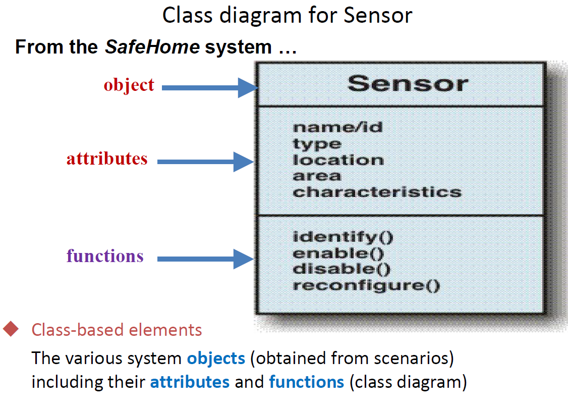
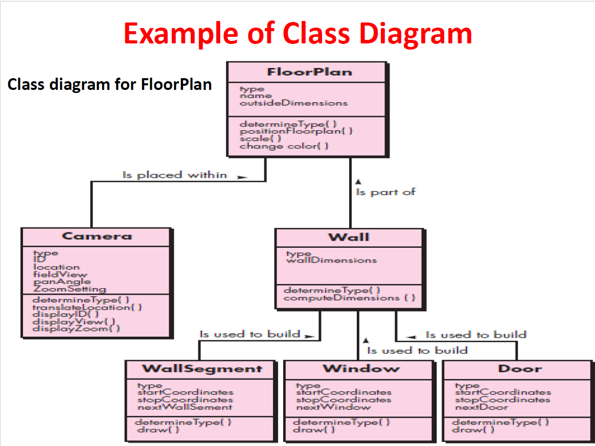
9.4 CRC Modeling
Class-responsibility-collaborator (CRC) modeling provides a simple means for identifying and organizing the classes that are relevant to system or product requirement. The intent is to develop an organized representation of classes.It make use of actual or virtual index cards.
Cards are divided into three sections.Along the top of the card you write the name of the class. In the body of the card you list the class responsibilities on the left and the collaborators on the right.
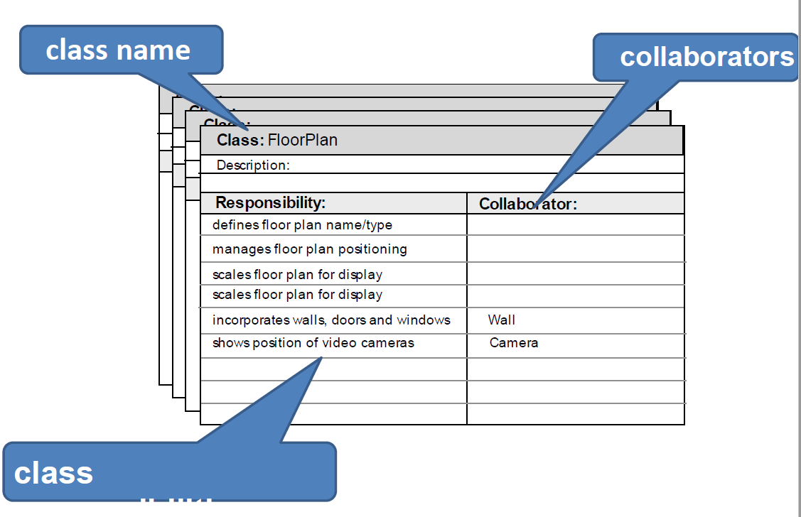
9.4.1 Class Types
Entity classes
also called model or business classes, are extracted directly from the statement of the problem (e.g., FloorPlan and Sensor).
Boundary classes
are used to create the interface (e.g., interactive screen or printed reports) that the user sees and interacts with as the software is used.
Controller classes(控制类)
manage a “unit of work” [UML03] from start to finish.
That is, controller classes can be designed to manage :
- the creation or update of entity objects;
- the instantiation of boundary objects as they obtain information from entity objects;
- complex communication between sets of objects;
- validation of data communicated between objects or between the user and the application.
9.4.2 Responsibilities
Responsibilities are the attributes and operations that are relevant for the class.Stated simply, a responsibility is “anything the class knows or does” [AMB95].
Classes fulfill their responsibilities in one of two ways:
(1) A class can use its own operations to manipulate its own attributes, thereby fulfilling a particular responsibility;
or
(2) a class can collaborate with other classes.
9.4.3 Collaborators
Collaborators are those classes that are required to provide a class with the information needed to complete a responsibility.In general, a collaboration implies either a request for information or a request for some action.
9.5 Associations and Dependencies
关联和依赖
Two analysis classes are often related to one another in some fashion
- In UML, these relationships (联系)are called associations
- Associations can be refined by indicating multiplicity
In many instances, a client-server relationship exists between two analysis classes. In such cases, a client-class depends on the server-class in some way and a dependency relationship is established.
9.5.1 Multiplicity
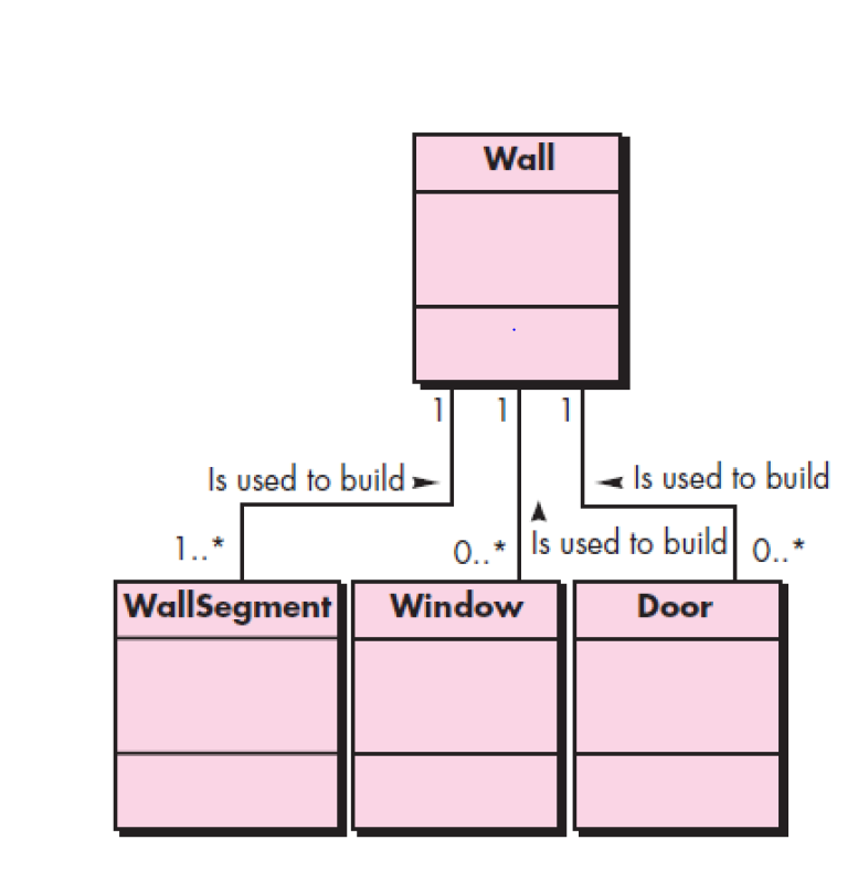
In UML, the asterisk indicates an unlimited upper bound on the range.
“one or more”: 1..* “zero or more”: 0..*
9.5.2 Dependencies
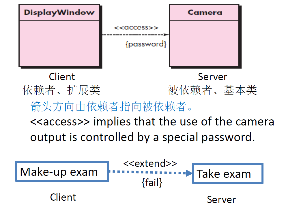
Fail which is in bracket is the condition.
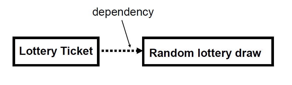
dependency: "uses temporarily"
- symbolized by dotted line(虚线)
- often is an implementation detail, not an intrinsic part of that object's state
不是对象状态的内部部分
9.6 Relationships between classes
Generalization(泛化)/Specialization(特殊化): an inheritance(继承) relationship
Association(关联): a usage relationship
- Aggregation(聚合)
- Composition(组合)
9.6.1 Generalization relationships
generalization (inheritance) relationships – arrows pointing upward to parent from child
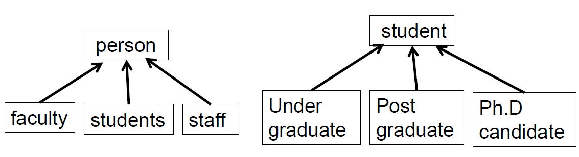
overlapped disjoin
9.6.2 Association types--- Aggregation
Represents a ‘has-a’ or ‘is-part-of’ relationship between entity types, where one represents the ‘whole’ and the other ‘the part’.
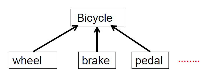
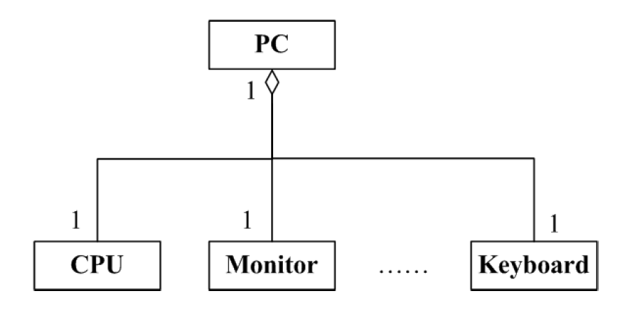
aggregation: "is part of" – symbolized by a clear white diamond (空心菱形)
9.6.3 Association types--- composition
composition: "is entirely made of" – stronger version of aggregation – the parts live and die with the whole – symbolized by a black diamond
组合是更强的聚合 部分与整体同生共死
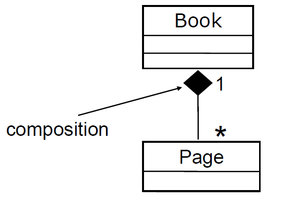
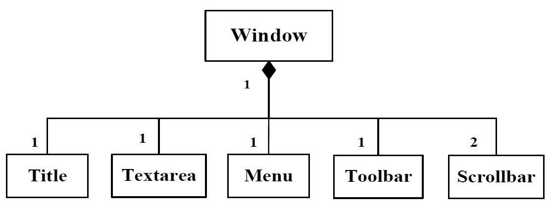
9.7 Class diagram example
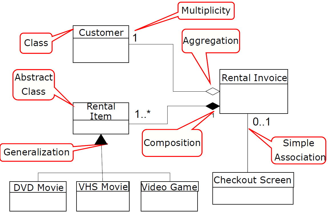
Chapter 10 Requirements Modeling:Behavioral Models
10.1 Behavioral Modeling
After our discussion of scenario-based and class- based models in Chapters 8 and 9, it ’s reasonable to ask, “Aren’t those requirement modeling representations enough?”
The only reasonable answer is, “ That depends.”For some types of software, use case and class-based models may be enough. But in other situations, complex application requirements may demand an examination of how an application behaves when an external event occur; how the data objects transform in the system.
Each of these modeling representations supplements (补充)the scenario-based and class-based models.Behavioral Modeling depicts the states of the system and its classes and the impact of events on these state. Behavioral models are models of the dynamic behavior(动态行为) of a system as it is executing.
10.2 CREATING A BEHAVIORAL MODEL
The modeling notation that has been discussed in the preceding chapters represents static elements of the requirements model.It is now time to make a transition to the dynamic behavior of the system or product.To accomplish this, you can represent the behavior of the system as a function of specific events and time.
Behavioral model indicates how software will respond to external events or stimuli.To create model, the analyst should perform the following steps:
(1) Evaluate all use cases to understand the sequence of interaction within the system
(2) Identify events that drive the interaction sequence and understand how these events relate to specific objects.
(3) Create a sequence for each use-case
(4) Build a state diagram for the system
(5) Review the behavioral model to verify accuracy or consistency.
Two types of behavioral model
- state diagram
- sequence diagram
10.3 Identifying Events with The Use-Cases
Use-case represents a sequence of activities that involves actors and the system.An event occurs whenever the system and an actor exchange information.**An event is not the information that has been exchanged, but rather the fact that information has been exchanged.**An actor should be identified for each event.Information that is exchanged should be noted.Any conditions or constraints should be listed.
10.4 State Diagram
State —a set of observable circumstances that characterizes the behavior of a system at a given time.
状态是一组可观察到的细节用于刻画系统在给定时刻的行为
State transition —the movement from one state to another.
Event —an outer stimulus that can cause the state change of an object, also called a trigger.
All the states belongs to a class or an object
The States of A System
An action occurs concurrently with the state transition or as a sequence of it and generally involves one or more operations of the object(only one).
动作与状态转换同时发生或作为状态转换的序列发生,并且通常涉及对象的一个或多个操作
State Representation
状态表达
In the context of behavioral modeling, two different characterizations of states must be considered:
- the state of each class as the system performs its function
- the state of the system as observed from the outside as the system performs its function
State Diagram for Analysis Classes
- One component of a behavioral model is a UML state diagram.
- UML state diagram represents states for each class and events that causes changes between these state.
- State diagrams do not show the flow of data within the system.
- Each arrow represents a transition from one state of an object to another.
- The labels shown for each arrow represent the event that triggers the transition.
State diagram is replenishment of class description. An event may be an action which causes state change.An event may be a message from another object,or meeting some conditions.Not all classes need state diagram.Some classes have clear states changing according to conditions and events. In UML state diagrams, rounded rectangles represent system states.They may include a brief description (following ‘do’) of the actions taken in that state.The labeled arrows represent an event that force a transition from one state to another.You can indicate start and end states using filled circles, as in activity diagrams.
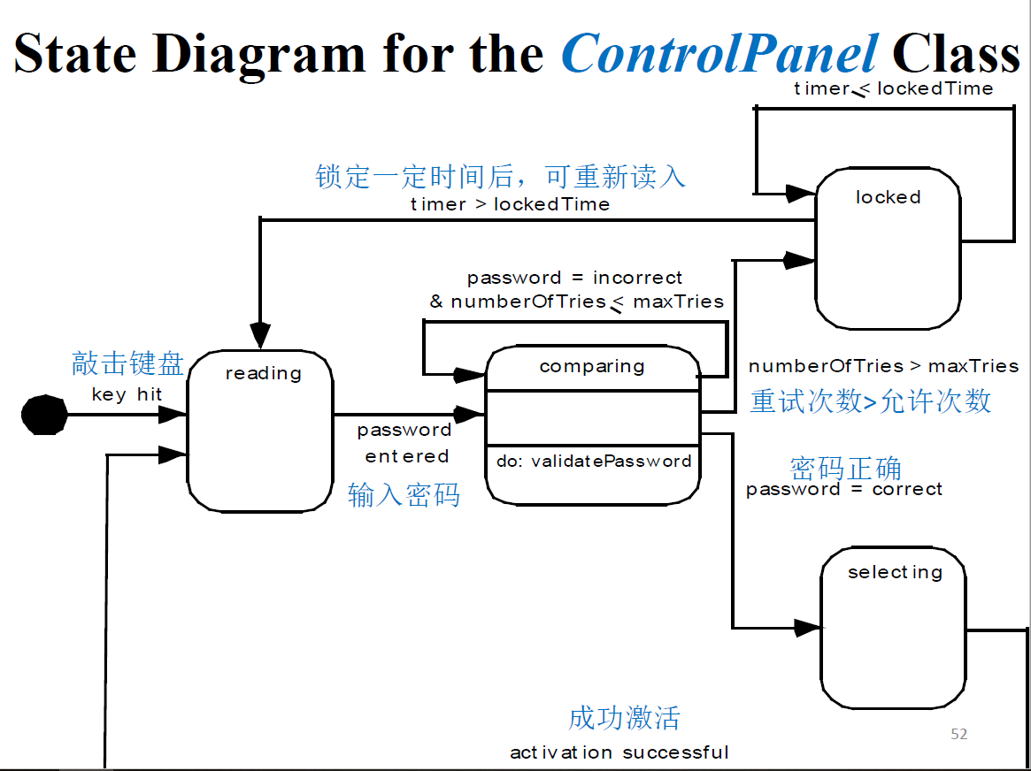
10.5 Sequence Diagram
It is the second type of behavioral representation, perhaps 2nd most used UML diagram (behind class diagram).
It indicates how events cause transitions from object to object .
(include many or several objects state/only one object).
Once event have been identified by examining a use-cases, the modeler creates a sequence diagram.
It is a representation of how events cause flow from one objects to another as function of time.It ’s a shorthand version of use-case. It represents key classes and the events that cause behavior to flow from class to class.
The objects and actors involved are listed along the top of the diagram, with a dotted line drawn vertically from these.The narrow vertical rectangles on the dotted lines represent the lifeline of the object concerned (i.e., the time that object instance is involved in the computation).Interactions between objects are indicated by annotated arrows.
You read the sequence of interactions from top to bottom on the dotted lines.The annotations(注释) on the arrows indicate the calls to the objects, their parameters, and the return values.
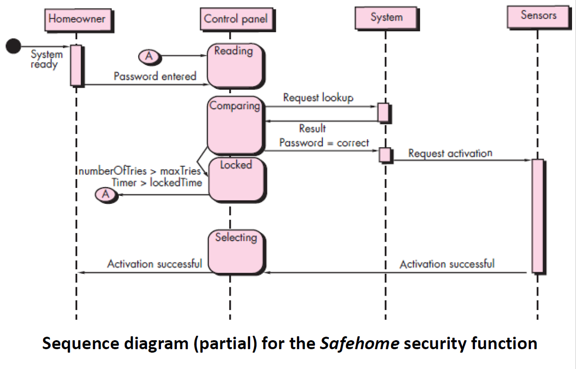
Chapter 11 Design Concepts
11.1 Overall of Design Concepts
Design is the place where creativity rules—where stakeholder requirements, business needs, and technical considerations all come together in the formulation of a product or system.
Design creates a representation or model of the software. But unlike the requirements model (that focuses on describing required data, function, and behavior), the design model provides detail about software data structures, architecture, interfaces, and components that are necessary to implement the system.Design is the place where software quality is established. 软件质量实在设计中建立的
Design model includes more detailes information.
11.2 What is the work product of Design?
A design model that encompasses data/class, architectural, interface, component-level, and deployment representations(5 elements in work product of design) is the primary work product that is produced during software design.The work product of design model includes 5 types of elements.
11.3 How do I ensure that I’ve done it right?
The design model is assessed by the software team in an effort to determine
- whether it contains errors, inconsistencies, or omissions;
- whether better alternatives exist;
- and whether the model can be implemented within the constraints, schedule, and cost that have been established.
11.4 Software design
Software Design covers the set of principles, concepts, and practices that lead to the development of a high quality system or product.
Design principles establish an overriding philosophy that guides the design work you must perform.
Design concepts must be understood before the mechanics of various representations of the software that serve as a guide for the construction activity that follows.
Design is pivotal(关键) to successful software engineering.
Goal of design is to produce a model or representation that exhibits:
- Firmness– program should not have any bug that inhibits(妨碍) its functions.
- Commodity– suitable to its intended use.(适用)
- Delight- pleasurable to use.
11.5 Design Within the context of Software Engineering
Software design sits at the technical kernel of software engineering and is applied regardless of the software process model that is used.核心技术
Beginning once software requirements have been analyzed and modeled, software design is the last of software engineering action within the modeling activity and sets the stage for construction (code generation and testing).
软件设计是建模活动的最后一个SE 活动
Requirements model provide information that is necessary to create the four design models required for a complete specification of design.
Software design model consists of 4 designs:
- Architectural Design
- Data/class Design
- Interface Design
Component Design
这四个模型可以由需求模型直接转变而来/由requirement 继承来的,作为design model 的输入,然后细化Deployment Design
The requirements model, manifested by scenario- based, class-based, and behavioral elements, feed the design task.
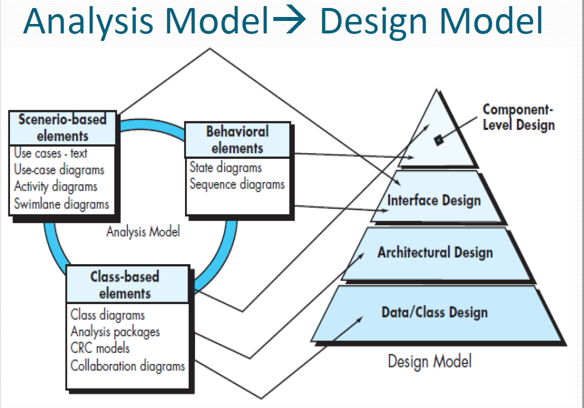
Data/class design
- transforms class models into design class realizations and requisite data structures required to implement the software.
Architectural design
- defines the relationships among the major structural elements of the software, the architectural styles and design patterns, and constraints.
Interface design
- describes how the software communicates with systems that interoperate with it, and with humans who use it.
Componen level design
- transforms structural elements of the software architecture into a procedural description of software components.
11.6 Why design is so important?
The importance of software design can be stated with a single word—quality.
Design is the place where quality is fostered 培养 in SE.It provides the representation of software that can be assessed for quality. Design is the only way that can accurately translate a customer ’s requirements into a finished software product.
It serves as the foundation for all the software engineering and software support activities that follow.
设计是所有SE 活动和随后的软件支持活动的基础
Without design, we risk building an unstable system :
- one that will fail when small changes are made;
- one that may be difficult to test Quality;
- one whose quality cannot be assessed until late in the software process, when time is short and many dollars have already been spent.
11.7 The Design Process
Software design is an iterative process through which requirements are translated into a “blueprint” for constructing the software.Initially, the blueprint depicts a holistic(整体) view of software. That is, the design is represented at a high level of abstraction.As design iteration occur, subsequent refinement leads to design representation at much lower levels of abstraction.(The higher abstraction,the less details it provide)
设计是在高抽象层次上的表达细化
11.8 Software Quality Guidelines and Attributes
(软件质量指导原则和属性)
Three characteristics that serve as a guide for the evaluation of a good design:
- The design must implement all of the explicit requirements contained in the analysis model, and it must accommodate all of the implicit requirements desired by stakeholders.(includes all requirements from all stackholders)全面
- The design should be a readable, understandable guide for those who generate code and for those who test and subsequently support the software.易懂
- The design should provide a complete picture of the software, addressing the data, functional, and behavioral domains from an implementation perspective.全貌
Each of these characteristics is actually a goal of the design process. But how is each of these goals achieved?
11.8.1 Quality Guidelines
we must establish technical criteria for good design, as the following guidelines:
1、A design should exhibit an architecture that
- has been created using recognizable architectural styles or patterns
- is composed of components that exhibit good design characteristics
- can be implemented in an evolutionary fashion.
2、A design should be modular; that is, the software should be logically partitioned into elements or subsystems.
3、A design should contain distinct representations of data, architecture, interfaces, and components.
4、A design should lead to data structures that are appropriate for the classes to be implemented and are drawn from recognizable data patterns.
5、 A design should lead to components that exhibit independent functional characteristics.
6、A design should lead to interfaces that reduce the complexity of connections between components and with the external environment.
7、 A design should be derived using a repeatable method that is driven by information obtained during software requirements analysis.
8、 A design should be represented using a notation that effectively communicates its meaning.
11.8.2 Quality Attributes
A set of software quality attributes is developed, which has been given the acronym FURPS –
- Functionality(功能性)
- Usability(易用性)
- Reliability(可靠性
- Performance(性能)
- Supportability (支持性)
The FURPS quality attributes represent a target for all software design.
Functionality
– is assessed by evaluating the feature set and capabilities of the program, the generality of the functions delivered, and the security of the overall system.
Usability
– is assessed by considering human factors, overall aesthetics, consistency & documentation.
Reliability
– is evaluated by measuring
- frequency and severity of failure
- accuracy of output results
- mean-time-to-failure (MTTF)
- ability to recover from failure
- predictability of the program
Performance
- is measured by processing speed, response time, resource consumption, throughput, efficiency.
Supportability
– combines the ability to extend the program (extensibility), adaptability and serviceability.
11.9 Design concepts
Each concept helps designers :
- define criteria 标准、尺度 that can be used to partition software into individual components;
- separate data structure detail from a conceptual representation of the software;
- establish uniform criteria that define the technical quality of a software design.
The beginning of wisdom for a [software engineer] is to recognize the difference between getting a program to work, and getting it right.Fundamental software design concepts provide the necessary framework for “getting it right”.
Abstraction
—data, procedure, control
Architecture
—the overall structure of the software
Patterns
—"conveys the essence" of a proven design solution
Separation of concerns
—any complex problem can be more easily handled if it is subdivided into pieces
Modularity
—compartmentalization of data and function数据分析和功能的分割
Information Hiding
—controlled interfaces
Functional independence
—single-minded function and low coupling
Refinement
—elaboration of detail for all abstractions
Aspects
—a mechanism for understanding how global requirements affect design
Refactoring
重构
—a reorganization technique that simplifies the design
OO design concepts
Design Classes
—provide design detail that will enable analysis classes to be implemented
11.9.1 Abstraction
When you consider a modular solution to any problems, many levels of abstraction can be posed.
(1) At the highest level of abstraction – a solution is stated in broad terms using the language of the problem environment.
(2) At lower level of abstraction – a more detailed description of the solution is provided.
(3) At the lowest level of abstraction, the solution is stated in a manner that can be directly implemented.
As different levels of abstraction are developed, you work to create both procedural and data abstractions.
11.9.1.1 Procedural abstraction
Procedural abstraction: refers to a sequence of instructions that have a specific and limited function.
The name of a procedural abstraction implies these functions, but specific details are suppressed.An example of a procedural abstraction would be the word open for a door. Open implies a long sequence of procedural steps (e.g., walk to the door, reach out and grasp knob, turn knob and pull door 拉门, step away from moving door, etc.)
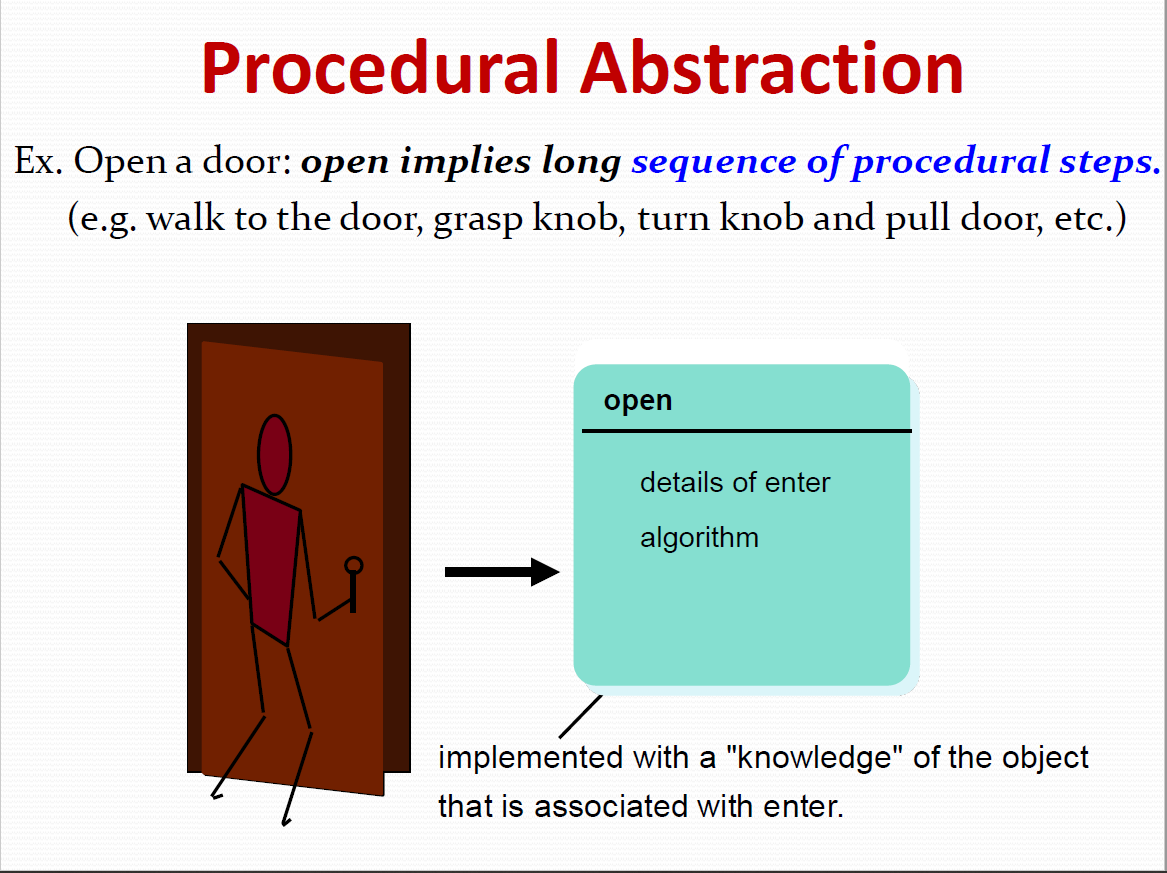
11.9.1.2 Data abstraction
Data abstraction is a named collection of data that describes a data object.
In the context of the procedural abstraction open, we can define a data abstraction called door.Like any data object, the data abstraction for door would encompass a set of attributes that describe the door (e.g., door type, swing direction, opening mechanism, weight, dimensions).It follows that the procedural abstraction open would make use of information contained in the attributes of the data abstraction door .
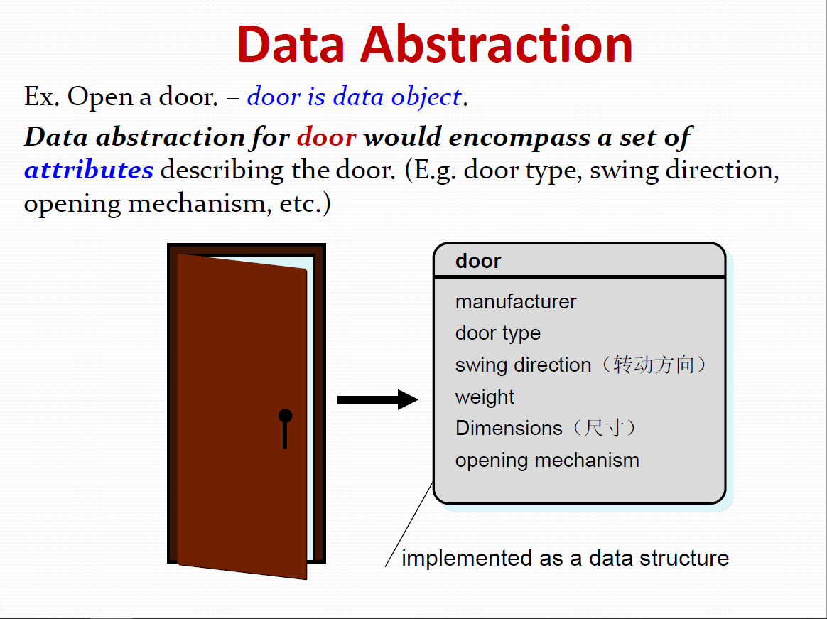
11.9.2 Architecture
Software architecture (SA)alludes to “The overall structure of the software and the ways in which that structure provides conceptual integrity for a system.”
Architecture is
- the structure or organization of program components(modules),
- the manner in which these components interact,
- the structure of data that are used by the components.
In a broader sense,Component can be generalized to represent major system elements and their interaction.One goal of software design is to derive an architectural rendering of a system, which serves as a framework from which more detailed design activities are conducted.A set of architectural patterns enables a software engineer to reuse design-level concepts.
An architecture design should have a set of properties(特性):
Structural properties
Defines the components of a system (e.g., modules, objects, filters) and the manne in which those components are packaged and interact with one another.
Extra-functional properties
Should address how the design architecture achieves requirements for performance,capacity,reliability, security, adaptability, and other system characteristic .
Families of related systems
Should draw upon repeatable patterns that are commonly encountered in the design of families of similar systems. In essence, the design should have the ability to reuse architectural building block .
11.9.3 Patterns
A Design Pattern describes a design structure that solves a particular design problem within a specific context and amid “forces” that may have an impact on the manner in which the pattern is applied and used.
The intent of each design pattern is to provide a description that enables a designer to determine:
(1)Whether the pattern is applicable to the current work
(2) Whether the pattern can be reused
(3) Whether the pattern can serve as a guide for developing a similar, but functionally or structurally different pattern.
11.9.4 Separation of Concerns
This design concept suggests that any complex problem can be more easily handled if it is subdivided into pieces that can each be solved and/or optimized independently.
A concern is a feature or behavior that is specified as part of the requirements model for the software.
By separating concerns into smaller, and therefore more manageable pieces, a problem takes less effort and time to solve. This leads to divid-and- conquer strategy: it’s easier to solve a complex problem when you break it into manageable pieces.
11.9.5 Modularity
Modularity is the most common manifestation(显示表明)of separation of concerns.Software is divided into separately named and addressable components, sometimes called modules, which are integrated to satisfy problem requirement.
Monolithic software (i.e., a large program composed of a single module) cannot be easily grasped by a software engineer.The number of control paths, span of reference, number of variables, and overall complexity would make understanding close to impossible.In almost all instances, you should break the design into many modules, hoping to make understanding easier and, as a consequence, reduce the cost required to build the software.
Recalling our discussion of separation of concerns, it is possible to conclude that if you subdivide software indefinitely the effort required to develop it will become negligibly small!
Unfortunately, other forces come into play, causing this conclusion to be (sadly) invalid.
Referring to Figure, the effort (cost) to develop an individual software module does decrease as the total number of modules increases.Given the same set of requirements, more modules means
smaller individual size.However, as the number of modules grows, the effort (cost) associated with integrating the modules also grows.These characteristics lead to a total cost or effort curve shown in the figure.
There is a number, M, of modules that would result in minimum development cost, but we do not have the necessary sophistication (复杂的成熟的技术)to predict M with assurance.We should modularize, but also should take care to stay in the vicinity of M.

Undermodularity or overmodularity should be avoided.
But how do we know "the vicinity of M"?How do I decompose a software to obtain the best set of modules?”The answers to these questions require an understanding of other design concepts considered later in this chapter.
Benefits of Modularity
We modularize a design so that development can be more easily planned.
- Software increments can be defined and delivered.
- Changes can be more easily accommodated.
- Testing and debugging can be conducted more efficiently.
- long-term maintenance can be conducted without serious side effects.
11.9.6 Information Hiding
The principle of Information Hiding suggests that modules should be “characterized by design decisions that (each) hides from all others.”.
In other words, modules should be specified and designed so that information (algorithms and data) contained within a module is inaccessible to other modules that have no need for such information.
The use of information hiding as a design criterion for modular systems provides the greatest benefits when modifications are required during testing and later during software maintenance.
Because most data and procedural details are hidden from other parts of software, unintentional errors introduced during modification are less likely to propagate to other locations within the software.
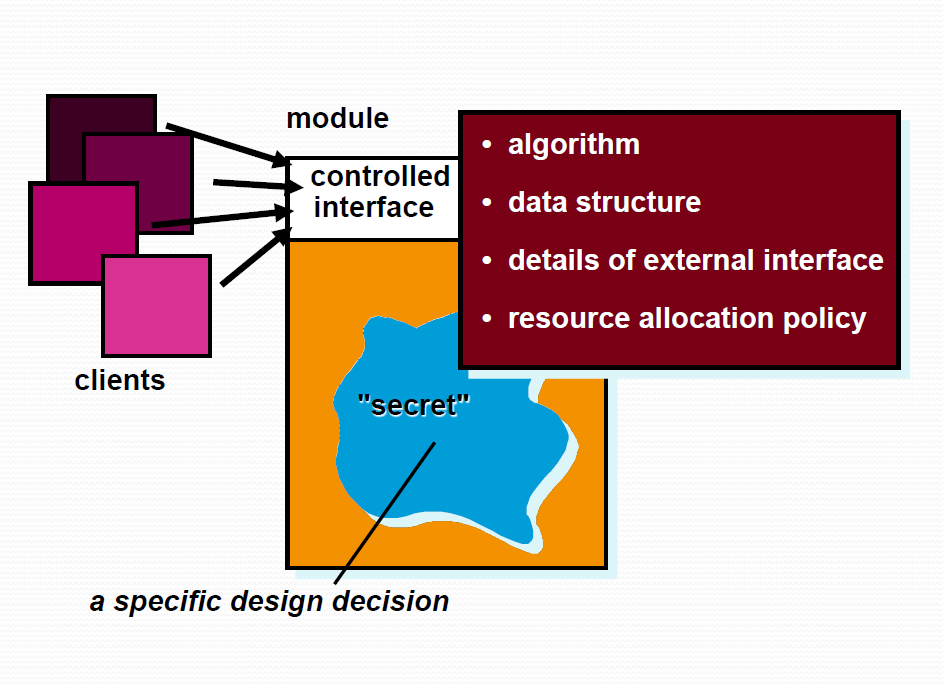
11.9.7 Functional Independence
The concept of functional independence is a direct outgrowth(直接产物) of separation of concerns, modularity and the concepts of abstraction and information hiding.
Functional independence is achieved by developing modules with "single-minded“ function and an "aversion" to excessive interaction with other modules.you should design software so that Each module addresses a specific sub-function of requirements and has a simple interface when viewed from other parts of the program structure.
why is independence important?
Software with independent modules
- Is easier to develop because function can be divided and interfaces are simplified;
- Is easier to test and maintain because secondary effects caused by design or code modification are limited;
- Error propagation is reduced(减少错误扩散)
- Reusable modules are possible (可复用模块)
To summarize, functional independence is a key to good design, and design is the key to software quality.
Independence is measured using two qualitative criteria: cohesion and coupling.
Cohesion
is an indication of the relative functional strength of a module.
Coupling
is an indication of the relative interdependence among modules.
11.9.7.1 Cohesion
Cohesion is a natural extension of the information hiding concept.
A cohesive module performs a single task, requiring little interaction with other components in other parts of a program.A cohesive module should (ideally) do just one thing.
High cohesion is characterized by a software component that performs multiple related functions. “Schizophrenic” components (modules that perform many unrelated functions) are to be avoided if a good design is to be achieved.
11.9.7.2 Coupling
Coupling is an indication of interconnection among modules in a software structure.
Coupling depends on the interface complexity between modules, the point at which entry or reference is made to a module, and what data pass across the interface.
In software design, we strive for lowest possible coupling.Simple connectivity among modules results in software that is easier to understand and less prone(倾向) to a "ripple effect" caused when errors occur at one location and propagate throughout a system.
11.9.7.3 Effective Modular Design
Effective modular design consist of three things:
- Functional Independence
- High cohesion
- Low coupling
11.9.8 Refinement
求精
Stepwise refinement is a top-down design strategy.
Refinement is actually a process of elaboration细化.
Begin with a statement of function (or description of information) that is defined at a high level of abstraction.The statement describes function or information conceptually but provides no information about the internal workings of the function or the internal structure of the information.
Then provide more and more detail as each successive refinement (elaboration) occurs.
Abstraction and refinement are complementary concepts.
Abstraction enables a designer to specify procedure and data internally and but suppress low-level details for outsiders.
Refinement helps the designer to expose low-level details as design progresses.
11.9.10 Refactoring
Refactoring is a reorganization technique that simplifies the design (or code) of a component without changing its function or behavior.
Definition:
"Refactoring is the process of changing a software system in such a way that it does not alter the external behavior of the code [design] yet improves its internal structure.”
When software is refactored, the existing design is examined for
- Redundancy冗余性
- unused design elements
- inefficient or unnecessary algorithms
- poorly constructed or inappropriate data structures
- any other design failure
The above can be corrected to yield a better design.
For example, a first design iteration might yield(产生) a component that exhibits low cohesion (i.e., it performs three functions that have only limited relationship to one another).After careful consideration, you may decide that the component should be refactored into three separate components, each exhibiting high cohesion.The result will be software that is easier to integrate, easier to test, and easier to maintain.
The intent of refactoring is to modify the code in a manner that does not alter its external behavior.
11.9.12 Design Classes
The type of classes:Analysis class(requirement),Design class(design)
The analysis model defines a set of analysis classes.Each of these classes describes some element of the problem domain, focusing on aspects of the problem that are user visible.The level of abstraction of an analysis class is relatively high.
As the design model evolves, you will define a set of design classes.Design classes refine the analysis classes by providing design detail that enable the classes to be implemented.Design classes implement a software infrastructure(基础) that supports the business solution.
Five different design classes can be developed. each of the five represents a different layer of the design architecture.
User interface classes (用户接口类)
define all abstractions that are necessary for human-computer interaction (HCI) and often implement the HCI in the context of a metaphor.
Business domain classes (业务域类)
identify the attributes and services (methods) that are required to implement some element of the business domain that was defined by one or more analysis classes.
Process classes (过程类)
implement lower-level business abstractions required to fully manage the business domain classes.
Persistent classes (持久类)
represent data stores (e.g., a database) that will persist beyond the execution of the software.
System classes(系统类)
implement software management and control functions that enable the system to operate and communicate within its computing environment and with the outside world.
Each design class should be reviewed to ensure that it is “well-formed”. A well-formed design classes has four characteristics
- Complete and sufficient 完整且充分
- Primitiveness 原始性
- High cohesion 高内聚
- Low coupling 低耦合
11.9.12.1 Complete and Sufficient
Complete
-A design class should include all necessary attributes and methods
For example, the class Scene defined for video-editing software is complete only if it contains all attributes and methods that can reasonably be associated with the creation of a video scene.
sufficient
–Sufficiency ensures that design class contains only those methods needed to achieve class intent, no more and no less.
11.9.12.2 Primitiveness
Primitiveness 原始性 (基本性)
Methods associated with a design class should be focused on accomplishing one service for the class.Once the service has been implemented with a method, the class should not provide another way to accomplish the same thing.
For example, the class VideoClip for video-editing software might have attributes start-point and end-point to indicate the start and end points of the clip (note that the raw video loaded into the system may be longer than the clip that is used).The methods, setStart-Point() and setEndPoint(), provide the only means for establishing start and end points for the clip.
11.9.12.3 High Cohesion
High cohesion
–A cohesive design class has a small, focused set of responsibilities and single-mindedly applies attributes and methods to implement those responsibilities.
For example, the class VideoClip might contain a set of methods for editing the video clip.As long as each method focuses solely on attributes associated with the video clip, cohesion is maintained.
11.9.12.4 Low coupling
Low coupling
– class collaboration kept to minimum
低耦合性 —— 类之间的协作保持最小范围
Within the design model, it is necessary for design classes to collaborate with one another.However, collaboration should be kept to an acceptable minimum.If a design model is highly coupled (all design classes collaborate with all other design classes), the system is difficult to implement, to test, and to maintain over time.
In general, design classes within a subsystem should have only limited knowledge of other classes.This restriction suggests that a method should only send messages to methods in neighboring classes.
11.10 The Design Model
Each element of the analysis model is transformed into a design equivalent and then refined iteratively.
In some cases, a clear distinction between the analysis and design models is possible.In other cases, the analysis model slowly blends into the design and a clear distinction is less obvious.The elements of the design model use many of the same UML diagrams that were used in the analysis model.
The difference between analysis diagram and design diagram is that
- these analysis diagrams are refined and elaborated as part of design;
- more implementation-specific detail is provided;
- Emphasize the following parts:
- architectural structure and style,
体系结构的结构和风格 - components that reside within the architecture,
体系结构中的构件 - interfaces between the components and with the outside world.
构件之间以及构件和外界之间的接口
- architectural structure and style,
In most cases preliminary architectural design sets the stage and is followed by interface design and component- level design, which often occur in parallel.The deployment model is usually delayed until the design has been fully developed.
You can apply design patterns at any point during design.These patterns enable you to apply design knowledge gained in the domain-specific problems that have been encountered and solved by others to your own design.
analysis pattern:speed up analysis/transform to design
11.11 Design Model Elements
- Architectural design elements
体系结构设计元素 - Data design elements
数据设计元素 - Interface design elements
接口设计元素 - Component design elements
构件级设计元素 - Deployment design elements
部署级设计元素
11.11.1 Architectural Design Elements
The architectural design for software is the equivalent to the floor plan of a house.The floor plan depicts the overall layout of the rooms; their size, shape, and relationship to one another; and the doors and windows that allow movement into and out of the rooms.
The floor plan gives us an overall view of the house.Architectural design elements give us an overall view of the software.
The architectural design element is usually depicted as a set of interconnected subsystems, often derived from analysis packages within the requirements model.Each subsystem may have its own architecture (e.g., a graphical user interface might be structured according to a preexisting architectural style for user interfaces).
11.11.2 Data Design Elements
Like other software engineering activities, data design (sometimes referred to as data architecting ) creates a model of data and/or information that is represented at a high level of abstraction (the customer/user ’s view of data).
This data model is then refined into progressively more implementation-specific representations that can be processed by the computer-based system.
11.11.3 Interface Design Elements
The interface design for software is analogous to a set of detailed drawings (and specifications) for the doors, windows, and external utilities of a house.
In essence, the detailed drawings (and specifications) for the doors, windows, and external utilities tell us how things and information flow into and out of the house and within the rooms that are part of the floor plan.
The interface design elements for software depict information flows into and out of a system and how it is communicated among the components defined as part of the architecture.
11.11.4 Component-Level Design Elements
The component-level design for software is the equivalent to a set of detailed drawings (and specifications) for each room in a house.
These drawings depict wiring and plumbing within each room, the location of electrical receptacles (插座)and wall switches, faucets, sinks, showers, tubs, drains, cabinets, and closets, and every other detail associated with a room.
The component-level design for software fully describes the internal detail of each software component.To accomplish this, the component-level design defines data structures for all local data objects and algorithmic detail for all processing that occurs within a component and an interface that allows access to all component operations (behaviors).
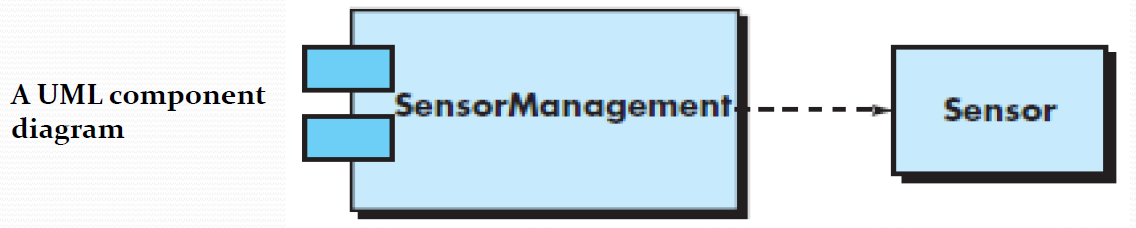
11.11.5 Deployment Design Elements
Deployment-level design elements indicate how software functionality and subsystems will be allocated within the physical computing environment that will support the software.
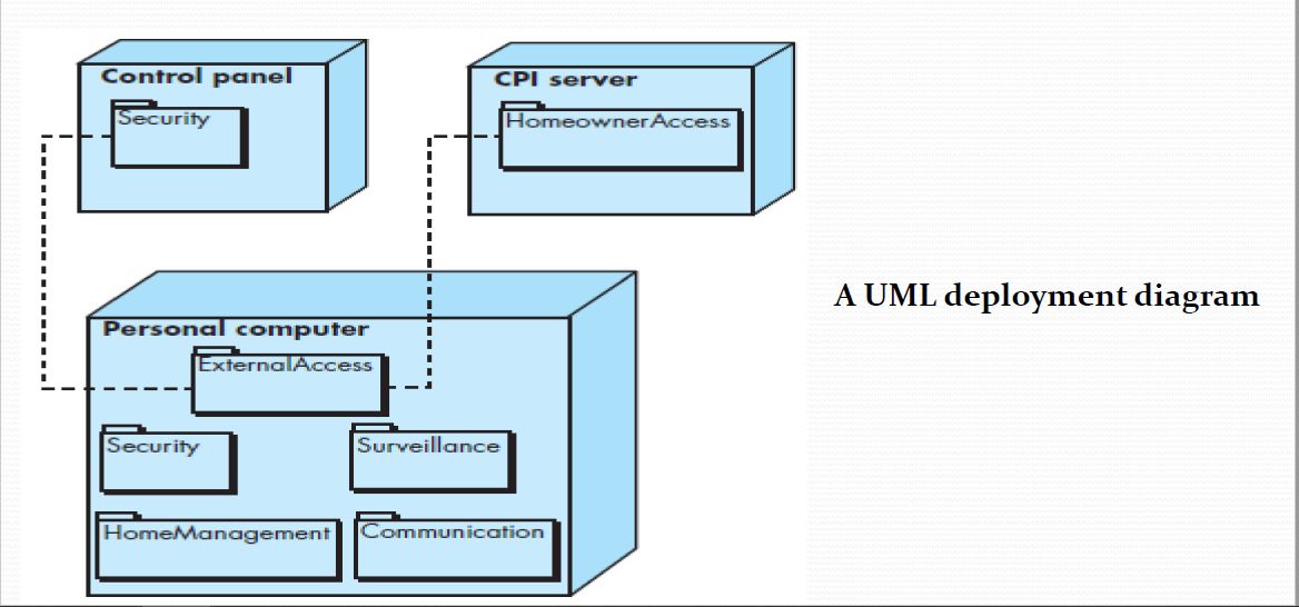
Chapter 12 Architectural Design
12.1 The concept of Architectural Design
- represents the structure of data and program components that are required to build a compute based system.
- considers the architectural style that the system will take the structure and properties of the component that constitute the system, and the interrelationship that occur among all architectural components of a system.]
结构模型 描述构件的属性和联系 包括数据体系结构和程序结构
12.2 Who does Architectural Design?
Although a software engineer can design both data and architecture, the job is often allocated to specialists when large, complex systems are to be built.The “system architect” selects an appropriate architectural style from the requirements derived during software requirements analysis.
12.3 Why is Architectural Design important?
- You wouldn’t attempt to build a house without a blueprint.
- You also wouldn’t begin drawing blueprints by sketching the plumbing layout for the house.
- Yo u’d need to look at the big picture—the house itself— before you worry about details.
That ’s what architectural design does—it provides you with the big picture and ensures that you’ve got it right.
12.4 What is the work product?
An architecture model encompassing data architecture and program structure is created during architectural design. In addition, component properties and relationships (interactions) are described.
12.5 How do I ensure that I’ve done it right?
At each stage, software design work products are reviewed for clarity, correctness, completeness, and consistency with requirements and with one another.
12.6 Architectural Design
Design is information drive . 设计是信息驱动的
Software design methods are derived from consideration of each of the three domains of the analysis mode .
- Data domain 数据
- Functiona domain 功能
- Behaviora domai . 行为
Architectural design is the preliminar blueprint from which software is constructed.
体系结构设计是构建软件的初始蓝图。
12.7 Software Architecture
【Definition of Architectur 】
The software architecture of a program or computing system is the structure or structure of the system, which comprise software components, the externally visible properties of those components, and the relationships among them.
A software component can be a program module or an object- oriented class;
The properties of components are those characteristics that are necessary to an understanding of how the components interact with other components.
The relationships between components can be a procedure call from one module to another.
12.7.1 What Is Architecture?
Architecture is not the operational software. Rather, it is a representation that enables a software engineer to:
- analyze the effectiveness of the design in meeting its stated requirements,
- consider architectural alternative at a stage when making design changes is still relatively easy,
- reduce the risks associated with the construction of the software.
12.7.2 Why Is Architecture Important?
- Software architecture provides a representations that facilitates communication among all stakeholders.
- The architecture highlights early design decisions that will have a profound impact on all software engineering work that follows.
- Architecture “constitutes a relatively small, intellectually graspable model of how the system is structured and how its components work together ” .
12.8 Architectural Genres(类型)
In the context of architectural design, genre implies a specific category within the overall software domain.Within each category, you encounter a number of subcategories.
For example, within the genre of buildings , you would encounter the following general types: houses(独栋房 子), condos, apartment buildings, office buildings, industrial building, warehouses, and so on.
例如,在建筑物类型中,会有以下几种通用类型:独栋房子、单元楼、公寓、办公楼、工厂厂房、仓库等等。
Within each general type, more specific styles might apply. Each style would have a structure that can be described using a set of predictable patterns.Architectural Genres for software-based systems include AI,communication, devices, financial, games, industrial, legal, medical, military, operating systems, transportation, and utilities, among many others.
软件系统的体系结构类型包括:人工智能、通信、设备、金融、 游戏、工业、法律、医疗、军事、操作系统、运输、实用程序及 许多其他类型。
Architectural Genres is Application domain. (即应用领域 )
12.9 Architectural Styles
When a builder uses the phrase “center hall colonial” to describe a house, most people familiar with houses in the United States will be able to conjure a general image of what the house will look like and what the floor plan is likely to be.
The builder has used an architectural style as a descriptive mechanism to differentiate the house from other styles (e.g., A-frame, raised ranch, Cape Cod).
建筑师使用体系结构风格作为描述手段,以区分“独栋 房子”与其他风格(例如,金字塔形建筑物、高地下室 的大平房、鳕鱼角式房屋)。
But more important, the architectural style is also a template for construction.Further details of the house must be defined, its final dimensions must be specified, customized features may be added, building materials are to be determined,The style—a “center hall colonial”—guides the builder in his work.
Each style describes a system category that encompasses (每种风格描述一种系统类别,包括 )
1. a set of components (e.g., a database,computational modules) that perform a function required by a system.功能构件
2. a set of connectors that enable “communication,coordination and cooperation” among component .连接件
3. constraints that define how components can be integrated to form the system.
4. semantic models that enable a designer to understand the overall properties of a system by analyzing the known properties of its constituent parts.语义模型
12.10 A Brief Taxonomy of Architectural Styles
- Data-centered architectures
以数据为中心的体系结构 - Data flow architectures
数据流体系结构 - Call and return architectures
调用和返回体系结构 - Object-oriented architectures
面向对象体系结构 - Layered architectures
层次体系结构
12.10.1 Data-Centered Architecture
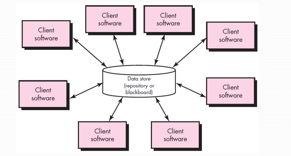
A data store (e.g., a file or database) resides at the center and is accessed frequently by other components that update, add, delete, or otherwise modify data within the store.Existing components can be changed and new client components added to the architecture without concern about other clients.
12.10.2 Data Flow Architecture
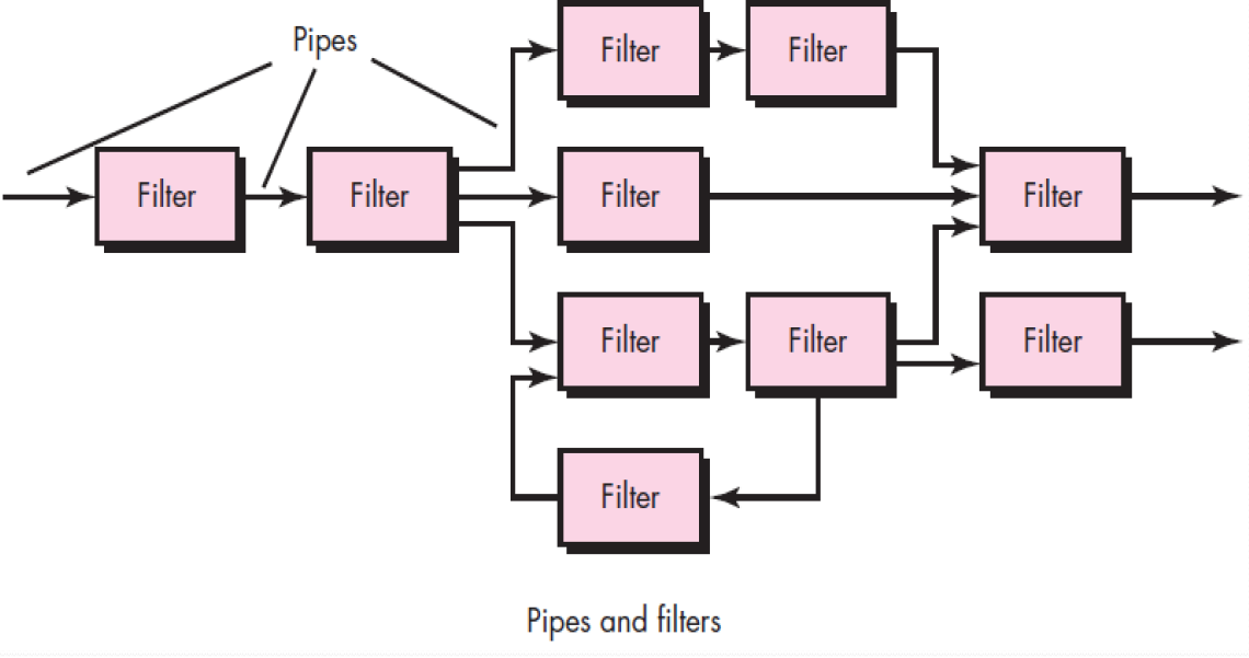
This architecture is applied when input data are to be transformed through a series of computational or manipulative components into output data.
12.10.3 Call and Return Architecture
This architectural style enables you to achieve a program structure that is relatively easy to modify and scale.
(1)Main program/subprogram architectures: decompose function into a control hierarchy where a “main” program invokes a number of program components that in turn may invoke still other components.
(2)Remote procedure call architectures: the components of a main program/subprogram architecture are distributed across multiple computers on a network.
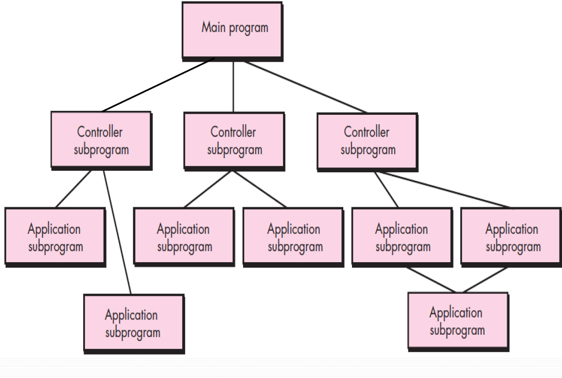
12.10.4 Object-oriented Architectures
The components of a system encapsulate data and the operations that must be applied to manipulate the data.
Communication and coordination between components are accomplished via message passing.
12.10.5 Layered Architecture
At the outer layer,components serve UI operations.
At the inner layer,components perform OS interfacing.
Intermediate layers provide utility services and application software functions.
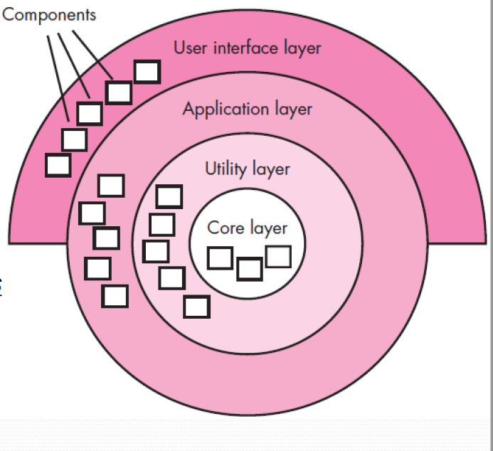
Chapter 15 Quality Concepts
15.1 what Is Quality
Quality of design refers to the characteristics that designers specify for a product.
In software development, , two kinds of quality may be encountered:
Quality of design 设计质量
encompasses the degree to which the design meets the functions and features specified in the requirements model.
Quality of conformance 符合质量
focuses on the degree to which the implementation follows the design and the resulting system meets its requirements and performance goals.
Robert Glass has a more “intuitive” (直观的) opinion:
User satisfaction = compliant product + good quality + delivery within budget and schedule
用户满意度 = 合格的产品 + 好的质量 + 按预算和进度安排交付
15.2 Software Quality
Software quality can be defined as:
An effective software process applied in a manner that creates a useful product that provides measurable value for those who produce it and those who use it.
价值是对生产者和使用者双方而言的
EVERY activity in Software Engineering process model, would contribute to the Software Quality !!!
The above definition emphasizes the following 3 important points.
- An effective software process
- A Useful Product
- Adding Value
15.2.1 Effective Software Process
An effective software process establishes the infrastructure that supports any effort at building a high quality software product.
The management aspects of process create the checks and balances that help avoid project chaos—a key contributor to poor quality.Software engineering practices allow the developer to analyze the problem and design a solid solution—both critical to building high quality software.
Finally, umbrella activities such as change management and technical reviews have as much to do with quality as any other part of software engineering practice.
15.2.2 Useful Product
A useful product delivers the content, functions, and features that the end-user desires.But as important, it delivers these assets in a reliable, error-free way.A useful product always satisfies those requirements that have been explicitly stated by stakeholders.In addition, it satisfies a set of implicit requirements (e.g., ease of use) that are expected of all high quality software.
15.2.3 Adding Value
By adding value for both the producer and user of a software product, high quality software provides benefits for the software organization and the end-user community.
The end result is:
(1) greater software product revenue,
(2) better profitability when an application supports a business process, and/or
(3) improved availability of information that is crucial for the business.
15.3 Garvin’s Quality Dimensions
David Garvin [Gar87] suggests that quality should be considered by taking a multidimensional viewpoint:
Performance Quality.
Does the software deliver all content, functions, and features that are specified as part of the requirements model in a way that provides value to the end-user?
Feature quality.
Does the software provide features that surprise and delight the first-time end-users?
Reliability.
Does the software deliver all features and capability without failure? Is it available when it is needed? Does it deliver functionality that is error-free?
Conformance.
Does the software conform to local and external software standards that are relevant to the application? Does it conform to de facto design and coding conventions? For example, does the user interface conform to accepted design rules for menu selection or data input?
Durability.
Can the software be maintained (changed) or corrected (debugged) without the inadvertent generation of unintended side effects? Will changes cause the error rate or reliability to degrade with time?
Serviceability(适用性).
Can the software be maintained (changed) or corrected (debugged) in an acceptably short time period. Can support staff acquire all information they need to make changes or correct defects?
Aesthetics审美.
Most of us would agree that an aesthetic entity has a certain elegance, a unique flow, and an obvious “presence” that are hard to quantify but evident nonetheless.
Perception感知.
In some situations, you have a set of prejudices that will influence your perception of quality.
15.4 The Software Quality Dilemma
(困境)
Bertrand Meyer discusses the quality dilemma like this:
If you produce a software system that has terrible quality, you lose because no one will want to buy it.
If you spend infinite time, extremely large effort, and huge sums of money to build the absolutely perfect piece of software, then it's going to take so long to complete and it will be so expensive to produce that you'll be out of business anyway.
Either you missed the market window, or you simply exhausted all your resources.
So people in industry try to get to that magical middle ground where the product is good enough not to be rejected right away, such as during evaluation,…but also not the object of so much perfectionism and so much work that it would take too long or cost too much to complete.
So software engineers should strive to produce high-quality systems.
15.5 Factors affect SQ
Software Quality is affected by the following factors:
- Cost of Quality
- Risk
- Negligence and Liability
- Quality and Security
- Management Actions
15.5.1 Cost of Quality
The cost of quality includes all costs incurred(引起) in the pursuit of quality or in performing quality- related activities and the downstream costs of lack of quality.
Quality costs may be divided into 3 mode of cost:
- Prevention(预防成本)
- Appraisal(评估成本)
- Failure(失效成本)
15.5.1.1 Prevention costs
Prevention costs include
(1) the cost of management activities required to plan and coordinate all quality control and quality assurance activities,
(2) the cost of added technical activities to develop complete requirements and design models,
(3) test planning costs,
(4) the cost of all training associated with these activities
15.5.1.2 Appraisal costs
Appraisal costs include activities to gain insight into product condition the “first time through” each process.
Examples of appraisal costs include:
(1) the cost of conducting technical reviews for software engineering work products,
(2) the cost of data collection and metrics
(3) the cost of testing and debugging.
15.5.1.3 Failure costs
Failure costs are those that would disappear if no errors appeared before shipping a product to customers.
Failure costs may be subdivided into internal failure costs and external failure costs.
- Internal Failure Costs are incurred when you detect an error in a product prior to shipment(发布).
- External Failure Costs are associated with defects found after (product) shipping to the customer.
15.5.1.3.1 Internal Failure Costs
Internal Failure Costs include:
(1) the cost required to perform rework (repair) to correct an error,
(2) the cost that occurs when rework inadvertently generates side effects that must be mitigated,
(3) the costs associated with the collection of quality metrics that allow an organization to assess the modes of failure.
15.5.1.3.2 External Failure Cost
Examples of External Failure Cost are complaint resolution, product return and replacement, help line support, and labor costs associated with warranty(保修) work.
A poor reputation and the resulting loss of business is another external failure cost that is difficult to quantify but nonetheless very real.
Bad things happen when low-quality software is produced.
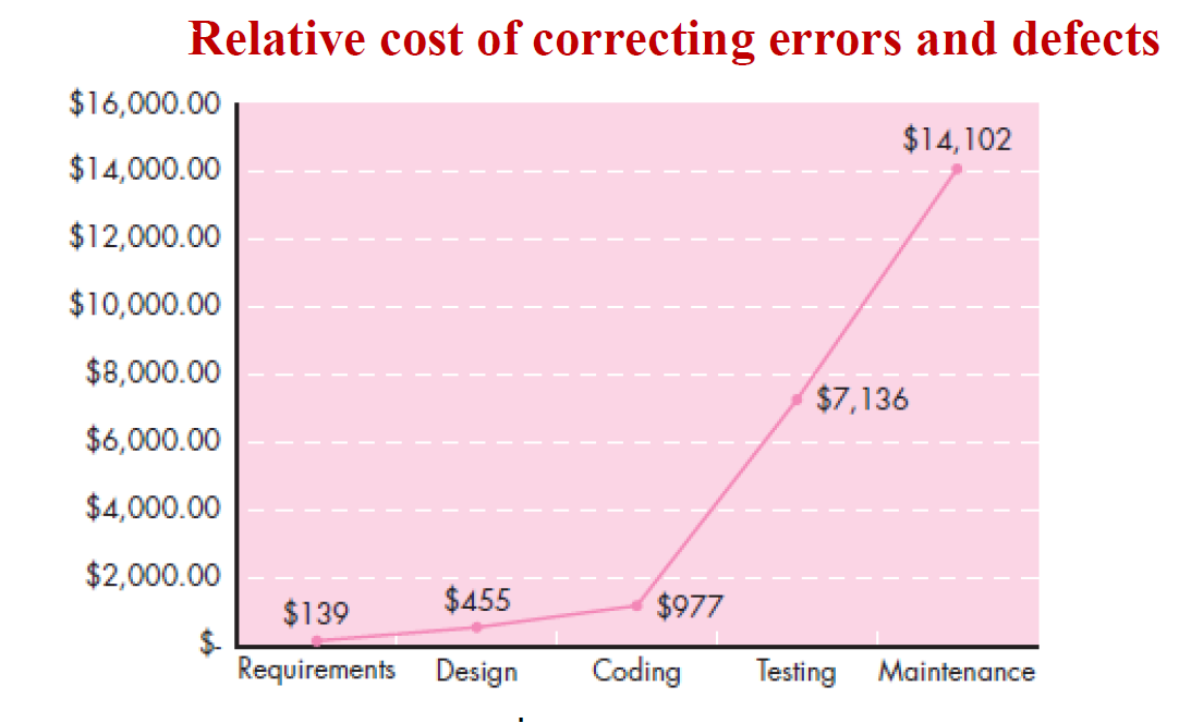
The relative costs to find and repair an error or defect increase dramatically as we go from prevention to detection to internal failure to external failure costs.
15.5.2 Risk
“People bet their jobs, their comforts, their safety, their entertainment, their decisions, and their very lives on computer software. It better be right.”
The implication is that low-quality software increases risks for both the developer and the end user.
Poor quality leads to risks, some of them very serious.
15.5.3 Negligence and Liability
疏忽和责任
The story is all too common. A governmental or corporate entity hires a major software developer or consulting company to analyze requirements and then design and construct a software-based “system” to support some major activity.
The system might support a major corporate function (e.g., pension management) or some governmental function (e.g., healthcare administration or homeland security).
Work begins with the best of intentions on both sides, but by the time the system is delivered, things have gone bad.
The system is late, fails to deliver desired features and functions, is error-prone, and does not meet with customer approval.
Litigation ensues.
In most cases, the customer claims that the developer has been negligent (in the manner in which it has applied software practices) and is therefore not entitled to payment.
The developer often claims that the customer has repeatedly changed its requirements and has subverted the development partnership in other ways.
In every case, the quality of the delivered system comes into question.
15.5.4 Quality and Security
As the criticality of Web-based and mobile systems grows, application security has become increasingly important.
Stated simply, software that does not exhibit high quality is easier to hack, and as a consequence, low-quality software can indirectly increase the security risk with all of its attendant costs and problems.
质量意识贯穿于整个软件开发
Security Gary McGraw comments [Wil05]:
“Software security relates entirely and completely to quality.
You must think about security, reliability, availability,dependability—at the beginning, in the design, architecture, test, and coding phases, all through the software life cycle [process].
Even people aware of the software security problem have focused on late life-cycle stuff.The earlier you find the software problem, the better.
And there are two kinds of software problems.One is bugs, which are implementation problems.The other is software flaws—architectural problems in the design.
People pay too much attention to bugs and not enough on flaws.”
To build a secure system, you must focus on quality, and that focus must begin during design.
15.5.5 Impact of Management Actions
Software quality is often influenced as much by management decisions as it is by technology decisions.Even the best software engineering practices can be subverted(破坏) by poor business decisions and questionable project management actions.
As each project task is initiated, a project leader will make decisions that can have a significant impact on product quality.
The decisions include:
Estimation decisions 估算决策
– irrational delivery date estimates cause teams to take short-cuts that can lead to reduced product quality
Scheduling decisions 进度安排决策
– failing to pay attention to task dependencies when creating the project schedule
Risk-oriented decisions 面向风险的决策
– reacting to each crisis as it arises rather than building in mechanisms to monitor risks may result in products having reduced quality
15.5.5.1 Estimation Decisions
In many cases there is enormous time-to-market pressure that forces a team to accept unrealistic delivery dates.As a consequence, shortcuts are taken, activities that lead to higher-quality software may be skipped, and product quality suffers.
If a delivery date is irrational, it is important to hold your ground.Explain why you need more time, or alternatively, suggest a subset of functionality that can be delivered (with high quality) in the time allotted.
15.5.5.2 Scheduling Decisions
When a software project schedule is established (Chapter 25), tasks are sequenced based on dependencies.For example, because component A depends on processing that occurs within components B, C, and D, component A cannot be scheduled for testing until components B, C, and D are fully tested.A project schedule would reflect this.
But if time is very short, and A must be available for further critical testing, you might decide to test A without its subordinate(附属的) components (which are running slightly behind schedule), so that you can make it available for other testing that must be done before delivery. After all, the deadline looms.
As a consequence, A may have defects(缺陷) that are hidden, only to be discovered much later. Quality suffers.
15.5.5.3 Risk-oriented Decisions
Risk management (Chapter 26) is one of the key attributes of a successful software project.
You really do need to know what might go wrong and establish a contingency(应急的) plan if it does.Too many software teams prefer blind optimism, establishing a development schedule under the assumption that nothing will go wrong.
Worse, they don’t have a way of handling things that do go wrong.As a consequence, when a risk becomes a reality, chaos reigns, and as the degree of craziness rises, the level of quality invariably(必然) falls.
15.5.5.4 Advice
The software quality dilemma can best be summarized by stating Meskimen’s law — There's never time to do it right, but always time to do it over again.
Our advice: taking the time to do it right is almost never the wrong decision.
15.6 Achieving Software Quality
实现软件质量
Software quality doesn’t just appear. It is the result of good project management and solid software engineering practice.
To achieve high software quality, 4 activities of management and practice are applied.
- Software Engineering Methods
- Project Management Techniques
- Quality Control (质量控制)
- Quality Assurance (质量保证)
Software engineering Methods
To build high quality software you must understand the problem to be solved and be capable of creating a quality design that conforms to the problem requirements.
Project management techniques
project plan includes explicit techniques for quality and change management
Quality control
series of inspections(检查), reviews,and tests used to ensure conformance of a work product to its specifications
Quality assurance
consists of the auditing(审计) and reporting procedures used to provide management with data needed to make proactive decisions
Chapter 16 Software Quality Assurance
16.1 SQA
It’s not enough to talk the talk by saying that software quality is important. You have to
(1) explicitly define what is meant when you say “software quality,”
(2) create a set of activities that will help ensure that every software engineering work product exhibits high quality,
(3) perform quality control and assurance activities on every software project,
(4) use metrics to develop strategies for improving your software process and, as a consequence,the quality of the end
product.
The software engineering approach works toward a single goal: to produce on-time, high-quality software.Some software developers continue to believe that software quality is something you begin to worry about after code has been generated. Nothing could be further from the truth!
Software Quality Assurance ( often called quality management ) is an umbrella activity that is applied throughout the software process. (Begin from design,go through the entire software life cycle)
A SQA includes:
(1)An SQA process
(2)Specific quality assurance and quality control tasks ( including technical reviews and multi- tiered testing strategy)
(3)Effective SE practice (methods and tools)
(4)Control of all software work products and the changes made to them
(5)A procedure to ensure compliance(符合) with software development standards
(6)Measurement and reporting mechanism.
16.2 Elements of SQA
| Standards | 标准 |
|---|---|
| Reviews and Audits | 评审和审核 |
| Testing | 测试 |
| Error(bug)/defect(flaw/design defect) collection and analysis | 错误/缺陷的收集和分析 |
| Change management | 变更管理 |
| Education | 教育 |
| Vendor management | 供应商管理 |
| Security management | 安全防卫 |
| Safety | 安全 |
| Risk management | 风险管理 |
16.3 SQA Tasks
16.3.1 Prepares an SQA plan for a project.
为项目准备SQA计划
The plan is developed during project planning and is reviewed by all stakeholders.
The plan identifies
- Evaluations to be performed
- Audits and reviews to be performed
- Standards that are applicable to the project
- Procedures for error reporting and tracking
- Work products that are produced by the SQA group
- Amount of feedback provided to the software project team
16.3.2 Participates in the development of the project’s software process description.
The SQA group reviews the process description for compliance with organizational policy, internal software standards, externally imposed standards (e.g., ISO-9001), and other parts of the software project plan.
16.3.3 Reviews software engineering activities to verify compliance with the defined software process.
The SQA group identifies, documents, and tracks deviations(偏离) from the process, and verifies that corrections have been made;
16.3.4 Audits designated software work products to verify compliance with those defined as part of the software process.
designated 指定的
The SQA group reviews selected work products;identifies, documents, and tracks deviations,verifies that corrections have been made;periodically reports the results of its work to the project manager.
16.3.5 Ensures that deviations in software work and work products are documented and handled according to a documented procedure.
Deviations may be encountered in the project plan, process description, applicable standards, or technical work products.
16.3.6 Records any noncompliance and reports to senior management.
Noncompliance items are tracked until they are resolved.
16.4 SQA Goals
The SQA activities are performed to achieve a set of pragmatic goals:
Requirements quality.
The correctness, completeness, and consistency of the requirements model will have a strong influence on the quality of all work products that follow.
Design quality.
Every element of the design model should be assessed by the software team to ensure that it exhibits high quality and that the design itself conforms to requirements.
Code quality.
Source code and related work products (e.g., other descriptive information) must conform to local coding standards and exhibit characteristics that will facilitate maintainability.
Quality control effectiveness.
A software team should apply limited resources in a way that has the highest likelihood of achieving a high quality result.
16.5 Statistical SQA
Statistical SQA reflects a growing trend throughout the industry to become more quantitative about quality.
For software, Statistical SQA implies the following steps:
1. Information about software errors and defects is collected and categorized.
2. An attempt is made to trace each error and defect to its underlying(根本) cause (e.g., non-conformance to specifications, design error, violation of standards, poor communication with the customer).
3. Using the Pareto principle (80 percent of the defects can be traced to 20 percent of all possible causes), isolate the 20 percent (the vital few).
4. Once the vital few causes have been identified, move to correct the problems that have caused the errors and defects.
16.6 Six-Sigma for Software Engineering
Six Sigma is the most widely used strategy for statistical quality assurance in industry today.
六西格玛是当今产业界应用最广泛的统计质量保证策略。(六个标准差)
The Six Sigma strategy “is a rigorous and disciplined methodology that uses data and statistical analysis to measure and improve a company’s operational performance by identifying and eliminating defects in manufacturing and service- related processes”.
The term “six sigma” is derived from six standard deviations— 3.4 instances (defects) per million occurrences—implying an extremely high quality standard.
The Six Sigma methodology defines three core steps:
(1) Define customer requirements and deliverables and project goals via well-defined methods of customer communication
(2) Measure the existing process and its output to determine current quality performance (collect defect metrics)
(3) Analyze defect metrics and determine the vital few causes.
And 2 additional core steps:(以及2个附加核心步骤:)
(1) Improve the process by eliminating the root causes of defects.
(2) Control the process to ensure that future work does not reintroduce the causes of defects.
These core and additional steps are sometimes referred to as the DMAIC (define, measure, analyze, improve, and control) method.
16.7 Software Reliability
There is no doubt that the reliability of a computer program is an important element of its overall quality.If a program repeatedly and frequently fails to perform,it matters little whether other software quality factors are acceptable.
Software reliability is defined in statistical terms as “the probability of failure-free operation of a computer program in a specified environment for a specified time”.
无错误操作的概率
To illustrate, program X is estimated to have a reliability of 0.999 over 8 elapsed processing hours.In other words, if program X were to be executed 1000 times and require a total of 8 hours of elapsed processing time (execution time), it is likely to operate correctly (without failure) 999 times.
What is meant by the term failure(失效)?
In the context of any discussion of software quality and reliability, failure is nonconformance(不符合) to software requirements.Correction of one failure may in fact result in the introduction of other errors that ultimately result in other failures.
16.8 Measures of Reliability & Availability
Reliability
A simple measure of reliability is mean-time- between-failure (MTBF)平均失效间隔时间,
where the acronyms MTTF and MTTR are mean- time-to-failure and mean-time-to-repair, respectively.
In addition to a reliability measure, we must develop a measure of availability.
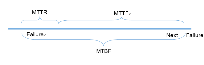
Availiability
可用性
Software availability is the probability that a program is operating according to requirements at a given point in time and is defined as
The MTBF reliability measure is equally sensitive to MTTF and MTTR.
The availability measure is somewhat more sensitive to MTTR, an indirectt measure of the maintainability of software.
可用性测量队MTTR较为敏感,MTTR对软件可维护性的间接测量
16.9 Software safety
Software safety is a software quality assurance activity that focuses on the identification and assessment of potential hazards that may affect software negatively and cause an entire system to fail.
If hazards can be identified early in the software process, software design features can be specified that will either eliminate or control potential hazards.
对软件质量度量的指标:可靠性、可用性、安全性
Although software reliability and software safety are closely related to one another, it is important to understand the subtle(细微) difference between them.
Software reliability uses statistical analysis to determine the likelihood that a software failure will occur. However, the occurrence of a failure does not necessarily result in a hazard or mishap(灾祸).
Software safety examines the ways in which failures result in conditions that can lead to a mishap. That is, failures are not considered in a vacuum, but are evaluated in the context of an entire computer-based system.
16.10 The ISO 9000 Quality Standard
A quality assurance system (QAS) is defined as the organization structure, responsibilities, procedures, processes, and resources for implementing quality management.
QAS are created to help organizations ensure their products and services satisfy customer expectations by meeting their specifications.ISO 9000 describes quality assurance elements in
generic terms that can be applied to any business regardless of the products or services offered.
To become registered to one of the quality assurance system models contained in ISO 9000, a company’s quality system and operations are scrutinized(检查) by third party auditors for compliance to the standard and for effective operation.
Upon successful registration, a company is issued(颁发) a certificate from a registration body represented by the auditors. Semi-annual surveillance audits ensure continued compliance to the standard.
16.11 The SQA Plan
The SQA Plan provides a road map for instituting(建立) software quality assurance.
Developed by the software team, the plan serves as a template for SQA activities that are instituted for each software project. A standard for SQA plans has been published by the IEEE [IEE94].
It recommends a structure that identifies:(8个活动/动作)
(1) the purpose and scope of the plan
(2) a description of all SE work products(e.g., models, documents, source code) that fall within the purview of SQA
(3) all applicable standards and practices that are applied during the software process
(4) SQA actions and tasks (including reviews and audits) and their placement throughout the software process
(5) the tools and methods that support SQA actions and tasks
(6) Software configuration management procedures
(7) methods for assembling, safeguarding, and maintaining all SQA-related records
(8) Organizational roles and responsibilities relative to product quality.
16.12 A Framework for Product Metrics
Although measure(测度), measurement(测量), and metric (度量)are often used interchangeably, the subtle difference among them exist.
- A measure provides a quantitative indication of the extent, amount, dimension, capacity, or size of some attribute of a product or process.
指标,名词 - Measurement is the act determining a measure.
动作,获得指标的动作 - Metric is defined as “a quantitative measure of the degree to which a system, component, or process possesses a given attribute”.
与单个测度相关,如发现错误的平均数
Example
粉笔盒
测度:长度10cm
测量:测量出10cm的动作
度量:有一批粉笔盒,各种型号,平均长度12cm
Chapter 17 Software Testing Strategies
17.1 Software Testing
【Definition】
Testing is the process of exercising a program with the specific intent of finding errors before delivery to the end user.
17.2 A Strategic Approach to Software Testing
A number of software testing strategies proposed in the literature provide you with a template for testing and all have the following features:
- To perform effective testing, you should conduct effective technical reviews. By doing this, many errors will be eliminated before testing commences.
- Testing begins at the component level and works "outward" toward the integration of the entire computer-based system.
- Different testing techniques are appropriate for different SE approaches and at different points in time.
- Testing is conducted by the developer of the software and (for large projects) an independent test group.
- Testing(find) and debugging(remove/only by developers) are different activities, but debugging must be accommodated(适应) in any testing strategy. Debugging is the process that results in the removal of the error.
17.2.1 Verification & Validation(V&V)
Verification refers to the set of tasks that ensure that software correctly implements a specific function.
Validation refers to a different set of tasks that ensure that the software that has been built is traceable to customer requirements.
Requirements Specifications do not always reflect the real wishes or needs of system customers and users.
Boehm [Boe81] states this in another way:
- Verification: "Are we building the product right?"
- Validation: "Are we building the right product?"
17.2.2 Who Tests the Software?
| developer | independent tester |
|---|---|
| Understands the system but, will test gentl “ and, is driven by "delivery”. | Must learn about the system, but, will attempt to break it and, is driven by qualit . |
| Test the individua units (components) of the program, sometimes conduc integration testing | Test the integrated system and Remove the inherent problems that are introduced by the developer when he tests. |
17.2.3 Software Testing Strategy —Big picture
A Software process & strategy for software testing may also be viewed in the context of the spiral.
Unit testing begins at the vortex of the spiral and concentrates on each unit (i.e., component) of the software.Testing progresses by moving outward along the spiral to integration testing, where the focus is on design and the construction of the software architecture.
Another turn outward on the spiral, we encounter validation testing, where requirements established as part of software requirements analysis are validated against the software. Finally, we arrive at system testing, where the software and other system elements are tested as a whole.To test computer software, you spiral out along streamlines that broaden the scope of testing with each turn.
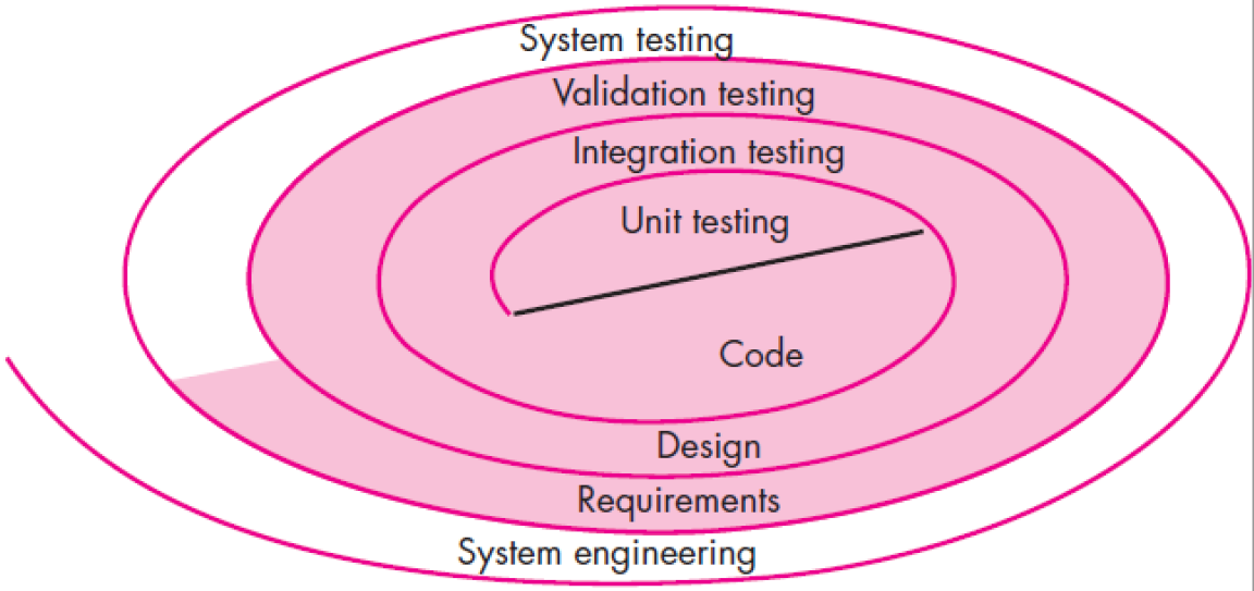
A Software process & strategy for software testing may also be viewed in the context of the spiral.螺旋前进
17.3 Software Testing Steps
Initially, Unit testing focus on each component individually, ensuring that it functions properly as a unit.Unit testing makes heavy use of white-box testing techniques, exercising specific paths in a module's control structure.
Integration testing focus on design and the construction of the software architecture.Black-box testing techniques are the most prevalent during integration.
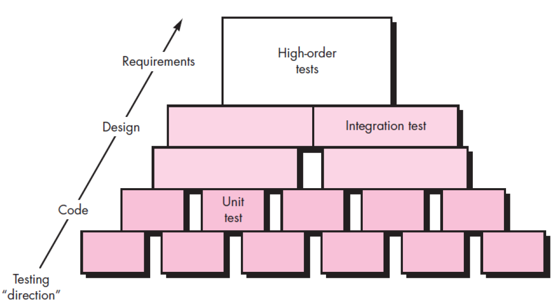
Software testing is actually a series of four steps that are implemented sequentially.
Hig order Tests
validation testing provides final assurance that software meets all functional, behavioral, and performance requirements.Black-box testing techniques are used exclusively during validation.
Software,once validated, must be combined with other system elements (e.g., hardware, people, databases). System testing verifies that all elements mesh properly and that overall system function / performance is achieved.
17.4 Strategic Issues
(1) Specify product requirements in a quantifiable manner long before testing commences.
(2) State testing objectives explicitly.
(3) Understand the users of the software and develop a profile for each user category.
- use cases
- interaction scenario.
(4) Develop a testing plan that emphasizes “rapid cycle testing.”
(5) Build “robust” software that is designed to test itself.
建立能测试其自身健壮性的软件
(6) Use effective technical reviews as a filter prior to testing.
(7) Conduct technical reviews to assess the test strategy and test cases themselves.
(8) Develop a continuous improvement approach for the testing process.
17.5 Testing Strategies for Conventional Software
17.5.1 Unit Testing
Focuses verification effort on the smallest unit of software design – component or module.
Using component-level design description as a guide,important control paths are tested to uncover errors within the boundary of the module.Unit test is white-box oriented, and the step can be
conducted in parallel for multiple components.
Unit test consists of
- Unit Test Considerations (单元测试问题)
- Unit Test Procedures (单元测试过程)
17.5.1.1 Unit Test Considerations
Do unit test,5 tasks/items you need to check
Module interface
– is tested to ensure that information properly flows into and out of the program unit under test.
Local data structure
– are examined to ensure that data stored temporarily maintains its integrity.
Independent paths
– are exercised to ensure that all statements in a module have been executed at least once.
Boundary conditions
–are tested to ensure that module operates properly at boundaries established to limit or restrict processing.
And finally,
all error
-handling paths are tested.
The design of unit tests can occur before coding or after source code has been generated.A review of design information provides guidance for establishing test cases. Each test case should be coupled with a set of expected results.Because a component is not a stand-alone program,driver and/or stub (桩) software must be developed for each unit test.
17.5.1.2 Unit Test Procedures
In most applications a driver is nothing more than a "main program" that accepts test case data, passes such data to the component (to be tested), and provides relevant results.
Stubs serve to replace modules that are subordinated (invoked by)从属于 the component to be tested.
A stub or “dummy subprogram” uses the subordinate module's interface, may do minimal data manipulation, provides verification of entry, and returns control to the module undergoing testing.
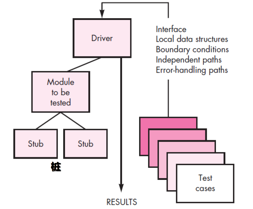
17.5.2 Integration Testing
“If they all work individually, why do you doubt that they’ll work when we put them together?”
The problem is “putting them together”—interfacing.
- Data can be lost across an interface.
- One component can have an inadvertent(疏忽的) , adverse(有害的) , effect on another.
- Subfunctions, when combined, may not produce the desired major function.
- Individually acceptable imprecision may be magnified to unacceptable levels.
- Global data structures can present problems.
The list goes on and on……
Integration testing is a systematic technique for constructing the software architecture.While at the same time conducting tests to uncover errors associated with interfacing.The objective is to take unit-tested modules and build a program structure that has been dictated by design.
Two Approaches
- Non-incremental Integration Testing (the “big bang ” approach )
- Incremental Integration Testing
17.5.2.1 Non-incremental Integration Testing
It constructs the program using “big bang” approach.
- All components are combined in advance.
- Entire program is tested as a whole.
- Chaos usually results! Errors are encountered.
- Correction is difficult because isolation of causes is complicated by the vast expanse
17.5.2.2 Incremental Integration Testing
opposite to “big bang” approach.
- Program is constructed and tested in small increments.
- Errors are easier to isolate and correct.
- Interfaces are more likely to be tested completely.
- A systematic test approach may be applied.
Different incremental integration strategies are discussed.
- Top-down integration
- Bottom-up integration
- Regression testing (回归测试)
- Smoking testing
Selection of an integration strategy depends upon software characteristics, project schedule.
17.5.2.2.1 Top-down integration
Top-down integration testing is an incremental approach to construction of the software architecture.
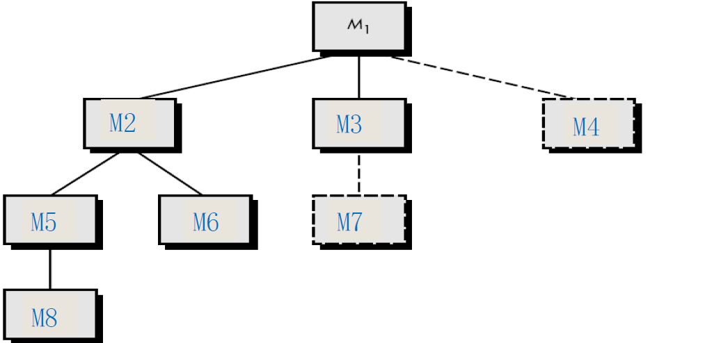
Depth-first integration
would integrate all components on a major control path of the structure.
For example, selecting the left hand path,First, Components M1, M2 , M5 would be integrated first.Next, M8 or M6 would be integrated.Then, the central and right hand control paths are built.
Breadth-first integration
incorporates all components directly subordinate at each level, moving across the structure horizontally.
Step would be:components M2, M3, and M4 would be integrated first,next control level, M5, M6, and so on follows.
17.5.2.2.2 Bottom up Integration
Bottom-up integration testing, as its name implies, begins construction and testing with atomic modules (i.e., components at the lowest levels in the program structure)
Because components are integrated from the bottom up, processing required for components subordinate to a given level is always available and the need for stubs is eliminated.
不再需要桩
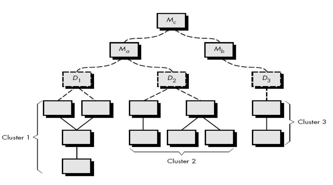
Components are combined to form clusters 1, 2,and 3. Each of the clusters is tested using a driver.Components in clusters 1 and 2 are subordinate to .Drivers and are removed and the clusters are interfaced directly to . Similarly, driver for cluster 3 is removed prior to integration with module .Both Ma and Mb will ultimately be integrated with component Mc, and so forth.
17.5.2.2.3 Regression Testing
Each time a new module is added as part of integration testing, the software changes.
New data flow paths are established, new I/O may occur, and new control logic is invoked. Side effects associated with these changes may cause problems with functions that previously worked flawlessly.
Regression testing is the re-execution of some subset of tests that have already been conducted to ensure that changes have not propagated unintended side effects.Regression testing helps to ensure that changes do not introduce unintended behavior or additional errors.Regression testing may be conducted manually, by re-executing a subset of all test cases or using automated capture/playback tools.
17.5.2.2.4 Smoke Testing
Smoke testing is said to be named by Microsoft.The name of the smoke testing means that it takes a short time and the time of smoking a cigarette is sufficient.
Others compare it to checking the basic function of a new circuit board.After welding, first do electrification check,if the new circuit board has a design defect, it may be short- circuited, the board smoke.
Smoke testing is when the developers discover bug and fix bug, and the testers test the problem. .In many cases, when developers try to solve problems within one module, they cause new problems in other modules, probably because they focus on the first problems and ignore other issues, which may lead to a new bug.
In essence, the smoke-testing approach encompasses the following activities:(冒烟测试包括以下3个活动):
(1) Software components that have been translated into code are integrated into a “build.” (构造)
A build includes all data files, libraries, reusable modules, and engineered components that are required to implement one or more product functions.
(2) A series of tests is designed to expose errors that will keep the build from properly performing its function.
The intent should be to uncover “show stopper” errors that have the highest likelihood of throwing the software project behind schedule.
(3) The build is integrated with other builds and the entire product (in its current form) is smoke tested daily.
The integration approach may be top-down or bottom-up.
The smoke test should exercise the entire system from end to end(彻底的).It does not have to be exhaustive(穷举), but it should be capable of exposing major problems.The smoke test should be thorough enough that if the build passes, you can assume that it is stable enough to be tested more thoroughly.
17.6 Validation testing
Validation testing follows integration testing.
The distinction between conventional and object-oriented software disappears.Validation Testing focuses on user-visible actions and user-recognizable output from the system.Validation testing succeeds when software functions in manner that can be reasonably expected by customer.
Like all other testing steps, validation tries to uncover errors, but the focus is at the requirements level— on things that will be immediately apparent to the end-user.
17.6.1 Alpha and Beta Testing
When the custom software is built for one customer, a series of acceptance tests are conducted to enable the customer to validate all requirements.
Conducted by the end-user rather than software engineers, an acceptance test can range from an informal “test drive” to a planned and systematically executed series of tests.Most software product builders use a process called alpha and beta testing to uncover errors that only the
end-user seems able to find.
17.6.2 Alpha Testing
Alpha testing
It is conducted at the developer ’s site by a representative group of end users.
Software is used in a natural setting with developers watching intently and recording errors and usage problems.Testing is conducted in a controlled environment.
17.6.3 Beta Testing
Beta testing( a variation on β testing is called acceptance testing.)
- It is conducted at end-user sites
- Developer is generally not present
It serves as a live application of the software in an environment that cannot be controlled by the developer.
The end-user records all problems that are encountered and reports these to the developers at regular intervals. After beta testing is complete,software engineers make software modifications and prepare for release of the software product to the entire customer base.
17.7 System Testing
Software is only one element of a large computer-based system.Finally, software is incorporated with other system elements (hardware, people, information), and a series of system integration and validation tests are conducted.
Types of system tests are:
- Recovery Testing
- Security Testing
- Stress Testing
- Performance Testing
- Deployment Testing
17.7.1 Recovery Testing
Recovery testing is a system test that forces the software to fail in a variety of ways and verifies that recovery is properly performed.
If recovery is automatic (performed by the system itself),reinitialization, checkpointing mechanisms, data recovery, and restart are evaluated for correctness.
If recovery requires human intervention, that is mean-time-to-repair (MTTR) is evaluated to determine whether it is within acceptable limits.
17.7.2 Security Testing
Security testing attempts to verify that protection mechanisms built into a system will, in fact, protect it from improper penetration.
During security testing, the tester plays the role(s) of the individual who desires to break through the system.Given enough time and resources, good security testing will ultimately penetrate(渗透) a system.The role of the system designer is to make penetration cost more than the value of the information that will be obtained.
17.7.3 Stress Testing
Stress testing are designed to confront programs with abnormal situations.
Stress testing executes a system in a manner that demands resources in abnormal quantity, frequency, or volume.Essentially, the tester attempts to break the program.
For example,
(1) special tests may be designed that generate 10 interrupts per second, when one or two is the average rate;
(2) input data rates may be increased by an order of magnitude to determine how input functions will respond;
(3) test cases that require maximum memory or other resources are executed;
(4) test cases that may cause thrashing in a virtual operating system are designed.
17.7.4 Performance Testing
Performance testing is designed to test the run-time performance of software within the context of an integrated system.
Performance testing occurs throughout all steps in the testing process.Even at the unit level, the performance of an individual module may be assessed as white-box tests are conducted.Performance tests are often coupled with stress testing and usually require both hardware and software instrumentation.
17.7.5 Deployment Testing
Sometimes called “Configuration Testing” .
- Exercises the software in each environment in which it is to operate.
- Examines all installation procedures and specialized installation software.
- Examines all documentation used to introduce the software to end users.
Chapter 18 Testing Conventional Application
18.1 White box testing
White-box testing, sometimes called glass-box testing or structural testing, is a test-case design method that uses the control to derive test cases.
Using this method, you can derive test cases that
1. Guarantee that all independent paths within a module have been exercised at least once.
2. Exercise all logical decisions on their true and false sides.
3. Execute all loops at their boundaries and within their operational bounds.
4. Exercise internal data structures to ensure their validity.
18.2 Basis path testing
Basis path testing is a white-box testing technique.
The steps is as follows.
1. Flow graph notation
2. Independent program paths
3. Deriving test cases
18.2.1 Flow Graph Notation
Start with simple notation for the representation of control flow . It represent logical control flow.Each circle, called flow graph node, represent one or more procedural statement.
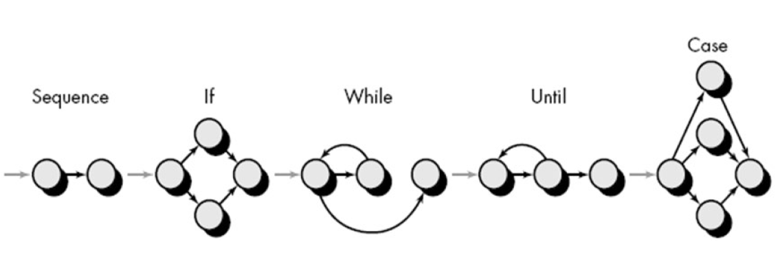
外部域
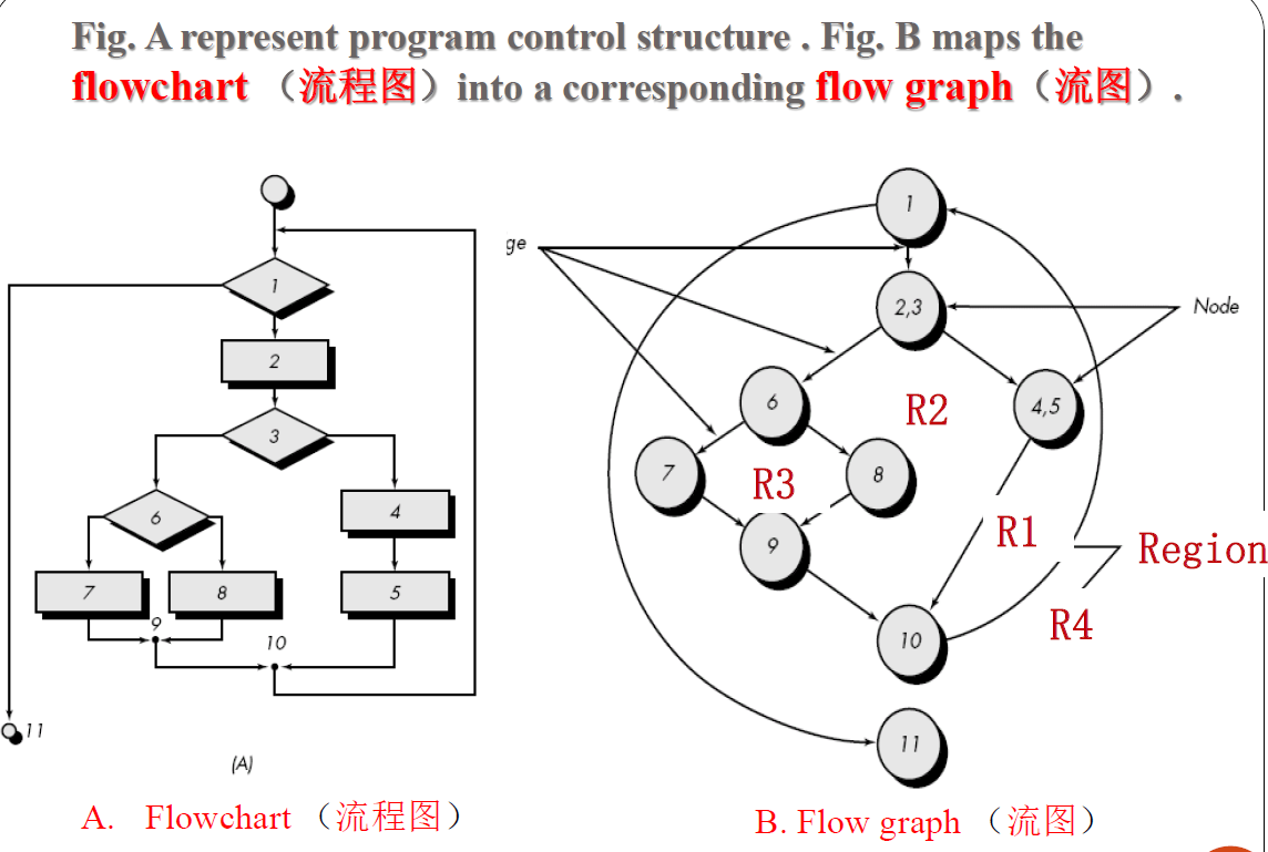
A flowchart is used to depict program control structure.
分支与可执行合并,分支一定是最后一条语句,两条分支语句不能合并
18.2.2 Independent program paths
An independent path is any path through the program that introduces at least one new set of
processing statement or new condition.
Note that each new path introduces a new edge.
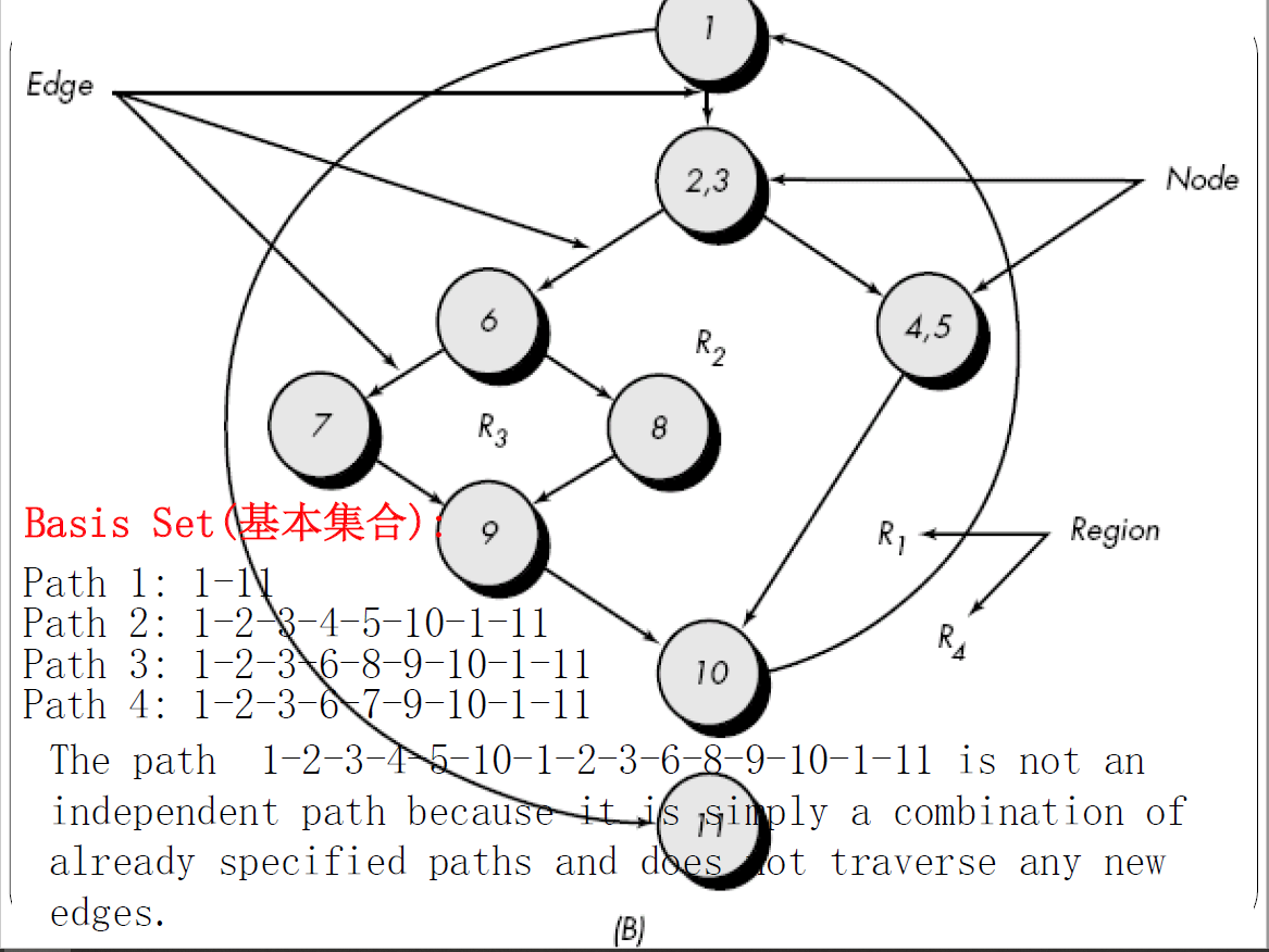
If you can design tests to force execution of these paths (a basis set),every statement in the program should be executed at least once and every condition will have been executed on its true and false.How do we know how many paths to looks for ?
Cyclomatic complexity环复杂性 is a software metrics that provides a quantitative measure of the logical complexity of a program.
It defines the number of independent paths in the basis set and also provides the number of test that must be conducted.
One of three ways to compute cyclomatic complexity:
1. The no. of regions corresponds to the cyclomatic complexity.环复杂性就等于流图中域(独立路径)的数量
2. Cyclomatic complexity, , for a flow graph,, is defined as
where is the number of flow graph edges, is the number of flow graph nodes.
3. Cyclomatic complexity, , for a flow graph,, is defined as
where is the number of predicate nodes(P为判定结点数)
So the value of provides us with upper bound of test cases.
表示测试用例数的上限
18.2.3 Deriving Test Cases
Basic path testing is a series of steps.The procedure average is depicted in PDL.Average, an extremely simple algorithm, contains compound conditions and loops.
The following steps can be applied to derive the basis set.
- Using the design or code as a foundation,draw a corresponding flow graph.
A flow graph is created by numbering those PDL statements that will be mapped into corresponding flow graph nodes.
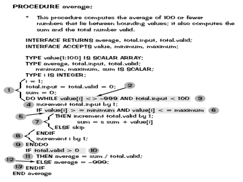
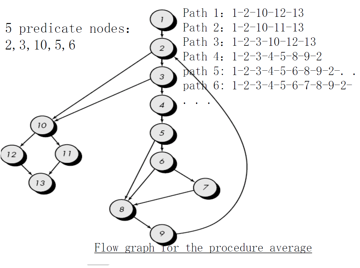
- Determine the cyclomatic complexity of the resultant flow graph.
- V(G) can be determined without developing a flow graph by counting all conditional statements in the PDL (for the procedure average, compound conditions count as two) and adding 1
- V(G) = 6 regions
- V(G) = 17 edges - 13 nodes + 2 = 6
- V(G) = 5 predicate nodes + 1 = 6
Determine a basis set of linearly independent paths
The value of V(G) provides the number of linearly independent paths through the program control structure.
- path 1: 1-2-10-11-13
- path 2: 1-2-10-12-13
- path 3: 1-2-3-10-11-13
- path 4: 1-2-3-4-5-8-9-2-. . .
- path 5: 1-2-3-4-5-6-8-9-2-. . .
- path 6: 1-2-3-4-5-6-7-8-9-2-. . .
The ellipsis (. . .) following paths 4, 5, and 6 indicates that any path through the remainder of the control structure is acceptable.
Prepare test cases that will force execution of each path in the basis set.
Data should be chosen so that conditions at the predicate nodes are appropriately set as each path is tested.Each test case is executed and compared to expected results.Once all test cases have been completed, the tester can be sure that all statements in the program have been executed at least once.
18.3 Black box testing
Also called behavioral testing or functional testing,focuses on the functional requirements of the software.
It enables the software engineer to derive sets of input conditions that will fully exercise all functional requirements for a program.Black-box testing is not an alternative to white-box techniques but it is complementary approach.
Black-box testing attempts to find errors in the following categories:
- Incorrect or missing functions
- Interface errors,
- Errors in data structures or external data base access.
- Behavior or performance errors
- Initialization and termination errors.
Because Black-box testing purposely ignored control structure, attention is focused on the information domain. Tests are designed to answer the following questions:How is functional validity tested?How is system behavior and performance tested?What classes of input will make good test cases?Is the system particularly sensitive to certain input values?How are the boundaries of a data class isolated?What data rates and data volume can the system tolerate?What effect will specific combinations of data have on system operation?
Black box testing methods
- Equivalence partitioning等价类划分
- Boundary value analysis (BVA)边界值分析
18.3.1 Equivalence Partitioning
Equivalence partitioning is a black-box testing method that divides the input domain of a program into classes of data from which test cases can be derived.
Test case design for equivalence partitioning is based on an evaluation of equivalence classes for an input condition.An equivalence class represents a set of valid or invalid states for input conditions.Typically, an input condition is either a specific numeric value, a range of values, a set of related values, or a Boolean condition.
To define equivalence classes follow the guideline 可以根据下述指导原则定义等价类
- If an input condition specifies a range, one valid and two invalid equivalence classes are
defined.
【1,10】invalid: x<1 and x>10; valid:1<=x<=10,

- If an input condition specifies a member of a set, one valid and one invalid equivalence class are defined.
e.g. in (valid) and not in (invalid) the set
- If an input condition is Boolean, one valid and one invalid class are defined.
meet the condition (valid) ; not meet (invalid)
18.3.2 Boundary Value Analysis (BVA)
A greater number of errors occurs at the boundaries of the input domain rather than in the “center.”
It is for this reason that boundary value analysis (BVA) has been developed as a testing technique.Boundary value analysis leads to a selection of test cases that exercise bounding values.
Boundary value analysis is a test case design technique that complements equivalence partitioning.Rather than selecting any element of an equivalence class, BVA leads to the selection of test cases at the "edges" of the class.
In other word, Rather than focusing solely on input conditions,BVA derives test cases from the output domain as well.
Guidelines for BVA
1. If an input condition specifies a range bounded by values a and b, test cases should be designed with values a and b and just above and just below a and b.
2. If an input condition specifies a number of values, test cases should be developed that exercise the minimum and maximum numbers. Values just above and below minimum and maximum are also tested.
3. Apply guidelines 1 and 2 to output conditions.
4. If internal program data structures have prescribed boundaries be certain to design a test case to exercise the data structure at its boundary.
Chapter 22 Project Managemen Concepts
22.1 The Four P’s
Effective software project management focuses on the four Ps:
- People — the most important element of a successful project
- Product — the software to be built确定产品目标和范围
- Process — the set of framework activities and software engineering tasks to get the job done.
- Project — all work required to make the product a reality.
The order is not arbitrary.顺序固定
22.2 People
- Stakeholders(利益相关者)
- Team Leaders
- The Software Team
22.2.1 Stakeholder (利益相关者)
Senior managers (高级管理者)who define the business issues that often have significant influence on the project.
Project (technical) managers who must plan, motivate, organize, and control the practitioners who do software work.
Practitioners(开发人员) who deliver the technical skills that are necessary to engineer a product or application.
Customers who specify the requirements for the software to be engineered and other stakeholders who have a peripheral interest in the outcome.
End-users who interact with the software once it is released for production use.
22.2.2 Team Leader
The MOI Model(Leadership Model)
Motivation.
The ability to encourage (by “push or pull”) technical people to produce to their best ability.
Organization.
The ability to mold existing processes (or invent new ones) that will enable the initial concept to be translated into a final product.
Ideas or innovation.
The ability to encourage people to create and feel creative even when they must work within bounds established for a particular software product or application.
22.2.3 Software Teams
The following factors must be considered when selecting a software project team structure .
- the difficulty of the problem to be solved
- the size of the resultant program(s) in lines of code or function points
- the time that the team will stay together (team lifetime)
- the degree to which the problem can be modularized
- the required quality and reliability of the system to be built
- the rigidity of the delivery date
- the degree of sociability (communication) required for the project
22.3 The Product
22.3.1 Software Scop
(软件范围)
The first software project management activity is to determine the software scope. Scope is defined by answering the following 3 types of questions:
Context.
项目环境
How does the software to be built fit into a larger system, product, or business context and what constraints are imposed as a result of the context?
Information objectives.
What customer-visible data objects are produced as output from the software?What data objects are required for input?
Function and performance.
What function does the software perform to transform input data into output? Are any special performance characteristics to be addressed?
Note:Software project scope (Software Scope) must be unambiguous and understandable at the management and technical levels.
22.3.2 Problem Decomposition
Sometimes called partitioning(划分) or problem elaboration(细化).
It is an activity that sits at the core of software requirements analysis.Once software scope is defined, the requirement is
- decomposed into constituent functions
- decomposed into user-visible data objects or
- decomposed into a set of problem classes
Divide-and conquer strategy: a complex problem is partitioned into smaller problems that are more manageable.
22.4 The Process
The framework activities (chapter 2)are applicable to all software projects. The problem is to select the most suitable process model for your project.
Your team must decide which process model is most appropriate for
(1) The customers who have requested the product and the people who will do the work.
(2) The characteristics of the product itself
(3) The project environment in which the software team works.
When a process model has been selected, the team then defines a preliminary project plan based on the set process framework activities.Once the preliminary project plan is established,process decomposition begins.A complete plan, reflecting the work tasks required to populate the framework activities, must be created.
22.5 The Project
In order to manage a successful software project, you have to understand what can go wrong so that problems can be avoided.
Projects get into trouble when …
- Software people don’t understand their customer ’s needs. This leads that the product scope is poorly defined.
- Changes are managed poorly.
- The chosen technology changes.
- Business needs change [or are ill-defined].
- Deadlines are unrealistic
- Users are resistant.
- Sponsorship is lost [or was never properly obtained].
- The project team lacks people with appropriate skills.
- Some developers never seem to learn from their mistakes.
22.6 Commin-Sense Approach to Projects
How does a manager act to avoid the above problems?
Start on the right foot.
This is accomplished by working hard (very hard) to understand the problem that is to be solved and then setting realistic objectives and expectations.
Maintain momentum.
保持动力
The project manager must provide incentives to keep turnover of personnel to an absolute minimum, the team should emphasize quality in every task it performs, and senior management should do everything possible to stay out of the team’s way.
Track progress.
For a software project, progress is tracked as work products (e.g., models, source code, sets of test cases) are produced and approved (using formal technical reviews) as part of a quality assurance activity.
Make smart decisions.
In essence, the decisions of the project manager and the software team should be to “keep it simple.”
Conduct a postmortem analysis.
进行事后分析
Establish a consistent mechanism for extracting lessons learned for each project.
22.7 principle
Boehm suggests the principle: After a series of questions that lead to a definition of key project characteristics and resultant project plan.
- Why is the system being developed?
- What will be done?
- When will it be accomplished?
- Who is responsible?
- Where are they organizationally located?
- How will the job be done technically and managerially?
- How much of each resource (e.g., people, software, tools, database) will be needed?
Chapter 23 Process and Projec Metrics
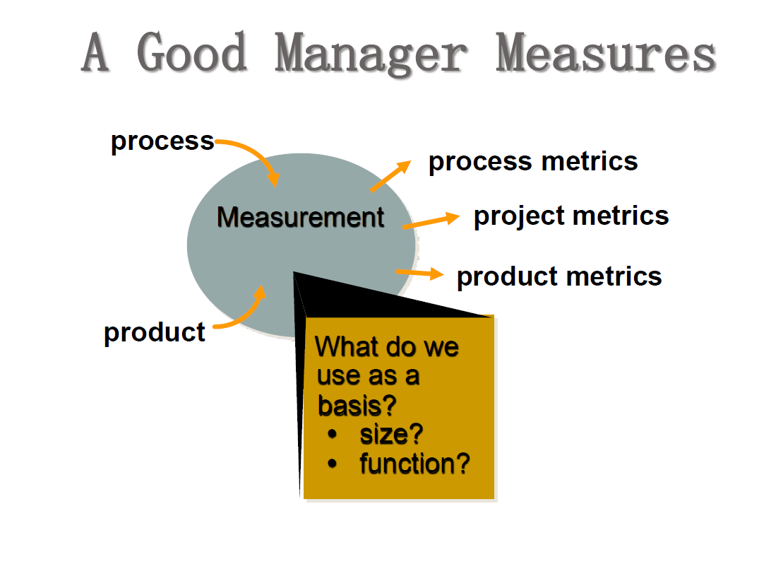
23.1 Metric in the Proces and Project Domain
We partition the software metrics domain into process, project, and product metrics.
23.1.1 Process Metrics
Process metrics are collect across all projects and over long period of time.
The intent of Process metrics is to provide a set of process indicators that lead to long-term software process improvement.
提供能够引导长期的软件过程改进的一组过程指标
We measure the efficacy(功效) of a software process indirectly.That is, we derive a set of metrics based on the outcomes that can be derived from the process.
These outcomes include
(1)measures of errors uncovered before release of the software.
(2)measures of defects delivered to and reported by end-users.
(3)measures of work products delivered (productivity).
(4)measures of human effort expended.
(5)measures of calendar time used.
(6)measures of schedule conformance.
(7)other measures.
23.1.2 Software Process Improvement(SPI)
Process metrics are used to make strategic decisions about how to complete (and ultimately, improve) common process framework activities.
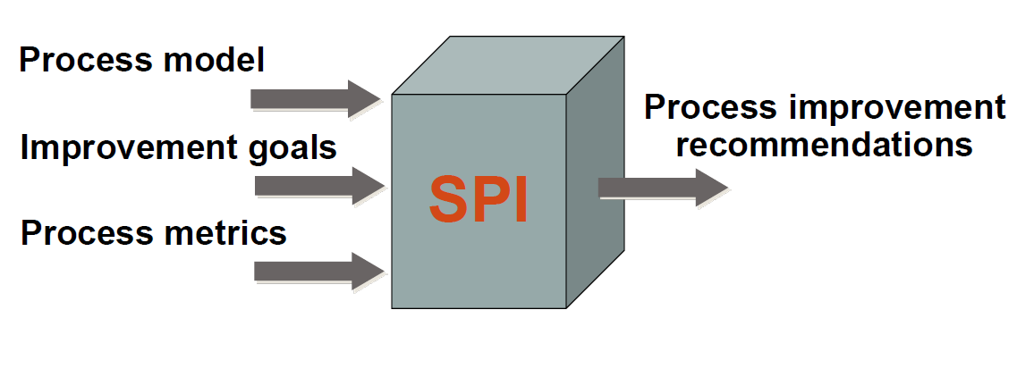
23.1.3 Project Metrics
Software process metrics are used for strategic purpose, software project measures (metrics)are tactical(战术的).
Project metrics are used by software project manager and team to adapt(improve) project work flow and technical activities.
Project metrics enable software project manager to
- assess the status of an ongoing project
- track potential risks
- uncover problem areas before they go “critical,”
- adjust work flow or tasks,
- evaluate the project team’s ability to control quality of software work products.
The intent of project metrics is twofold(双重的).
(1) monitor progress
- it is used to minimize the development schedule by making the adjustments necessary to avoid delays and mitigate(减少) potential problems and risks.
(2) control product quality
- it is used to assess product quality on an ongoing basis and, when necessary, modify the technical approach to improve quality.
Typical Project Metrics
- Effort/time per software engineering task
- Errors uncovered per review hour
- Scheduled vs. actual milestone dates
- Changes (number) and their characteristics
- Distribution of effort on software engineering tasks
23.2 Software Measurement
We have partitioned the software metrics domain into process, project, and product metrics.
Product metrics are often combined to develop project metrics.
Project metrics are then consolidated to create process metrics.
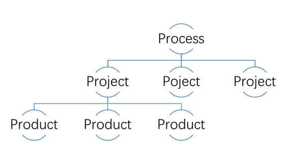
23.2.1 Size-Oriented Metrics
- errors per KLOC (thousand lines of code)
- defects per KLOC
- $ per LOC每行代码成本
- pages of documentation per KLOC
- errors per person-month
- errors per review hour
- LOC per person-month
- $ per page of documentation
23.2.2 Other Software Measurement
- 23.2.1 Size-Oriented Metrics
(LOC—line of code) - 23.2.2 Function-Oriented Metrics
(FP—Function Point) - 23.2.4 Object-Oriented Metrics
- 23.2.5 Use case- Oriented Metrics
23.3 Metrics for Software Quality
23.3.1 Measuring Quality
We apply product metrics to evaluate the quality of software engineering work products in objective, rather than subjective ways.
Correctness
— the degree to which a program operates according to specification.
Maintainability
—the degree to which a program is amenable to change.
Integrity
—the degree to which a program is impervious to outside attack.
Usability
—the degree to which a program is easy to use.
23.3.2 Defect Removal Efficiency
缺陷排除效率
where:
- is the number of errors found before delivery of the software to the end-user
- is the number of defects found after delivery.
The higher/larger,the better
Chapter 24 Estimation for Software Projects
24.1 Concepts
Software Project Management begins with a set of activities that are collectively called Project Planning.
Software Project Planning includes five major activities:
- estimation,
- scheduling,
- risk analysis,
- quality management planning,
- and change management planning.
Estimation
estimate cost and effort , the resources, and the time.
Scheduling
distributes estimated effort across the planned project duration by allocating the effort to specific software engineering tasks.
risk analysis
identify risk, estimate risk, and establish a contingency plan before the problem actually occur.
quality management planning
provides a road map for instituting software quality assurance.
change management planning
is a set of activities that have been developed to manage change throughout the life cycle. The goal is to maximize productivity by minimizing mistakes.
Before the project can begin, the team should estimate the work to be done, the resources that will be required, and the time that will elapse from start to finish.Once these activities are finished, the team should establish a project schedule that define SE tasks and milestones, and identify who is responsible for conducting each task.
24.2 Observations on Estimation
Estimation of resources, cost, and schedule for a software engineering effort requires :
- experience
- access to good historical information (metrics)
- the courage to commit to quantitative predictions when qualitative information is all that exists.
当只存在定性的信息时,要有进行定量预测的勇气
Estimation carries inherent risk and this risk leads to uncertainty.
24.3 The Project Planning Process
The objective of software project planning is to provide a framework that enables the manager to make reasonable estimates of resources, cost, and schedule.Why?
So the end result gets done on time, with quality!
A Project Plan is established as a consequence of tasks.Project Planning Task Set include the following tasks:
(1) Establish project scope
(2) Determine feasibility
(3) Analyze risks
(4) Define required resources
- Determine require human resources
- Define reusable software resources
- Identify environmental resources
(5) Estimate cost and effort
- Decompose the problem
- Develop two or more estimates using size, function points,process tasks or use-cases.
- Reconcile the estimates
(6) Develop a project schedule
- Establish a meaningful task set
- Define a task network
- Use scheduling tools to develop a timeline chart
- Define schedule tracking mechanisms
24.4 Software Scope and Feasibility
The first Project Planning Task is to establish project scope.
Software scope describes
- the functions and features that are to be delivered to end-users功能和性能
- the data that are input and output信息目标
- the “content” that is presented to users as a consequence of using the software信息目标
- the performance, constraints, interfaces, and reliability that bound the system.性能、项目环境
Scope is defined using one of two techniques:
- A narrative description of software scope is developed after communication with all stakeholders.
- A set of use-cases is developed by end-users.
24.5 Resources
The second Project Planning Task is to estimate the resources required to accomplish the software development effort.
There are 3 major categories of SE resources
- people,
- reusable software components
- and the development environment (hardware and software tools).
人员、可复用的软件构件、开发环境(硬件和软件工具)
Each resource is specified with four characteristics:
(1)description of the resource
(2)a statement of available
(3)time when the resource will be required
(4)duration of time that the resource will be applied.
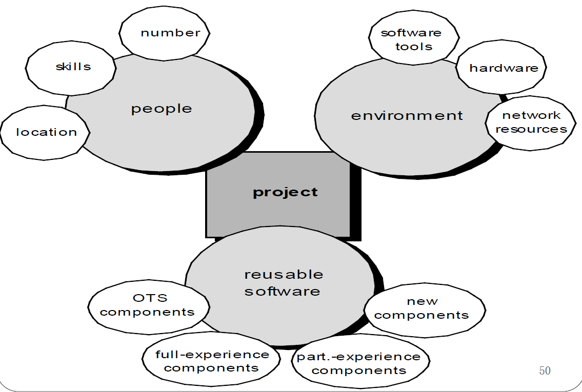
24.6 Software Project Estimation
Software cost and effort estimation will never be an exact science.
To achieve reliable cost and effort estimations, a number of options arise:
(1) Delay estimation until late in the project(we can achieve 100% accuracy after the project is complete!)
(2) Base estimates on past similar project experience.
(3) Use decomposition techniques to generate project cost and effort estimates.
(4) Use one or more empirical models( Historical data)经验模型 for software cost and effort estimates.
(5) Automated estimation tools implement one or more decomposition techniques or empirical models, and is an attractive option.
Chapter 25 Project Scheduling
25.1 Why Are Projects Late?
Although there are many reasons why software is delivered late, most can be traced to one or more of the following root causes:
- an unrealistic deadline established by someone outside the software development group.
- changing customer requirements that are not reflected in schedule changes;
- an underestimate of the amount of effort and/or the number of resources that will be required to do the job;
- predictable and/or unpredictable risks that were not considered when the project commenced;
- technical difficulties that could not have been foreseen in advance;
- human difficulties that could not have been foreseen in advance;
- miscommunication among project staff that results in delays;
- a failure by project management to recognize that the project is falling behind schedule and a lack of action to correct the problem.
25.2 Project Scheduling
Software Project Scheduling is an activity that distributes estimated effort across the planned project duration by allocating the effort(工作量) to specific software engineering tasks.
25.2.1 Scheduling Principles
Like all other areas of software engineering, a number of basic principles guide software project scheduling:
compartmentalization划分
—define distinct tasks
interdependency
—indicate task interrelationship
Time allocation
—allocate some number of work units(person-days of effort) to each task.
effort validation
—be sure resources are available
defined responsibilities
—people must be assigned
defined outcomes
—each task must have an output
defined milestones
—review for quality
25.2.2 The Relationship between People and Effort
The Putnam-Norden-Rayleigh (PNR) Curve provides an indication of the relationship between effort applied and delivery time for a software project.
The curve indicates a minimum value that indicates the least cost for delivery (i.e., the delivery time that will result in the least effort expended).As we move left of (i.e., as we try to accelerate delivery), the curve rises nonlinearly.
As an example, we assume that a project team has estimated a level of effort will be required to achieve a nominal delivery time that is optimal in terms of schedule and available resources.
Although it is possible to accelerate delivery, the curve rises very sharply to the left of .In fact, the PNR curve indicates the project delivery time cannot be compressed much beyond 0.75 .
If we attempt further compression, the project moves into “the impossible region” and risk of failure becomes very high.
The PNR curve also indicates that the lowest cost delivery option,
The implication here is that delaying project delivery can reduce costs significantly.
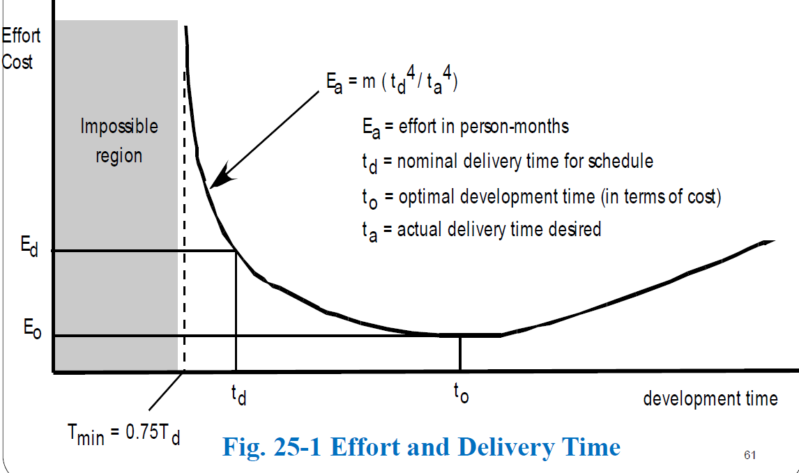
25.2.3 Effort Distribution
工作量分配 4 2 40 rule (法则)
A recommended distribution of effort across the software process is often referred to as the 40-20-40 rule.
Forty percent of all effort is allocated to front-end analysis and design. A similar percentage is applied to back-end testing.You can correctly infer that coding (20 percent of effort) is deemphasized.
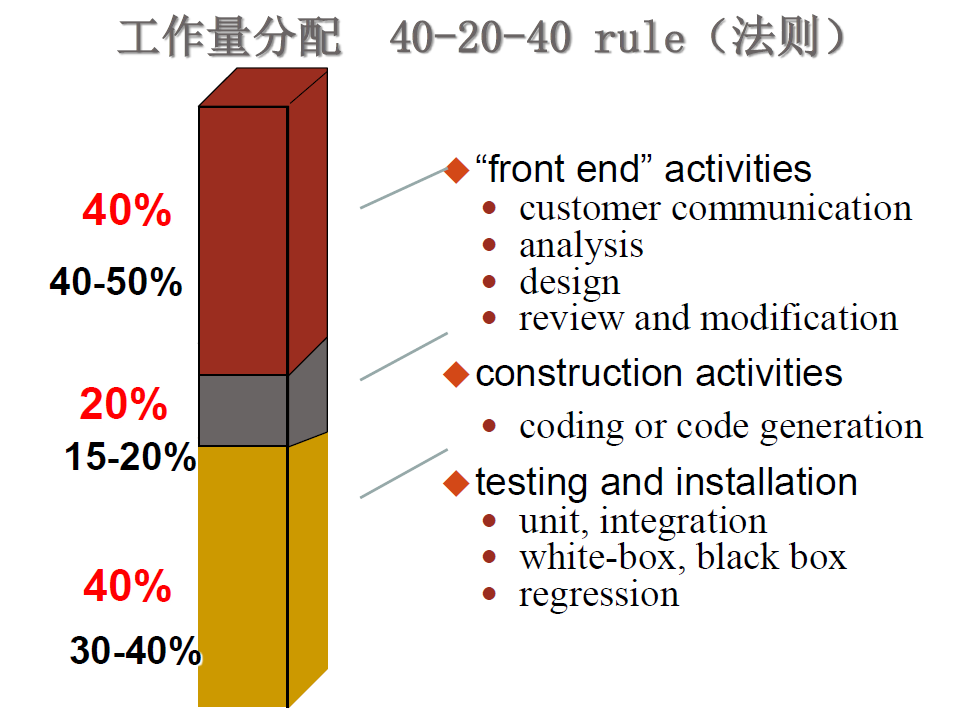
25.3 Steps for Software Project Scheduling
(1) Defining Task Sets for Software Project
(定义软件项目任务集)
- Define a initial task set(定义一个初始的任务集)
- Refine the major task (细化主要任务)
(2) Define a Task Network( 定义任务网络)
(3) Scheduling (进度安排)
- Time-line chart (时间线图、时序图)
- Tracking the schedule (跟踪进度)
25.3.2 Task Set Refinement
(p499)
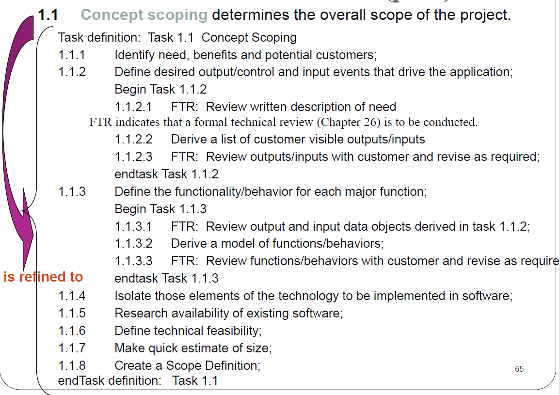
25.4 Define a Task Network
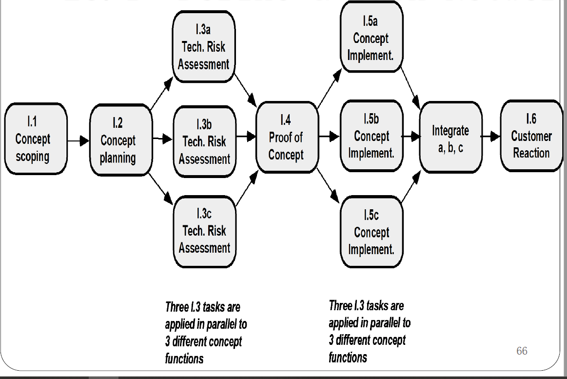
25.5 Scheduling
25.5.1 Time-line chart
- All project tasks are listed in the left-hand column.
- The horizontal bars indicate the duration of each task.
- When multiple bars occur at the same time on the calendar, task concurrency is implied.
- The diamonds indicate milestones.
Time-line Charts
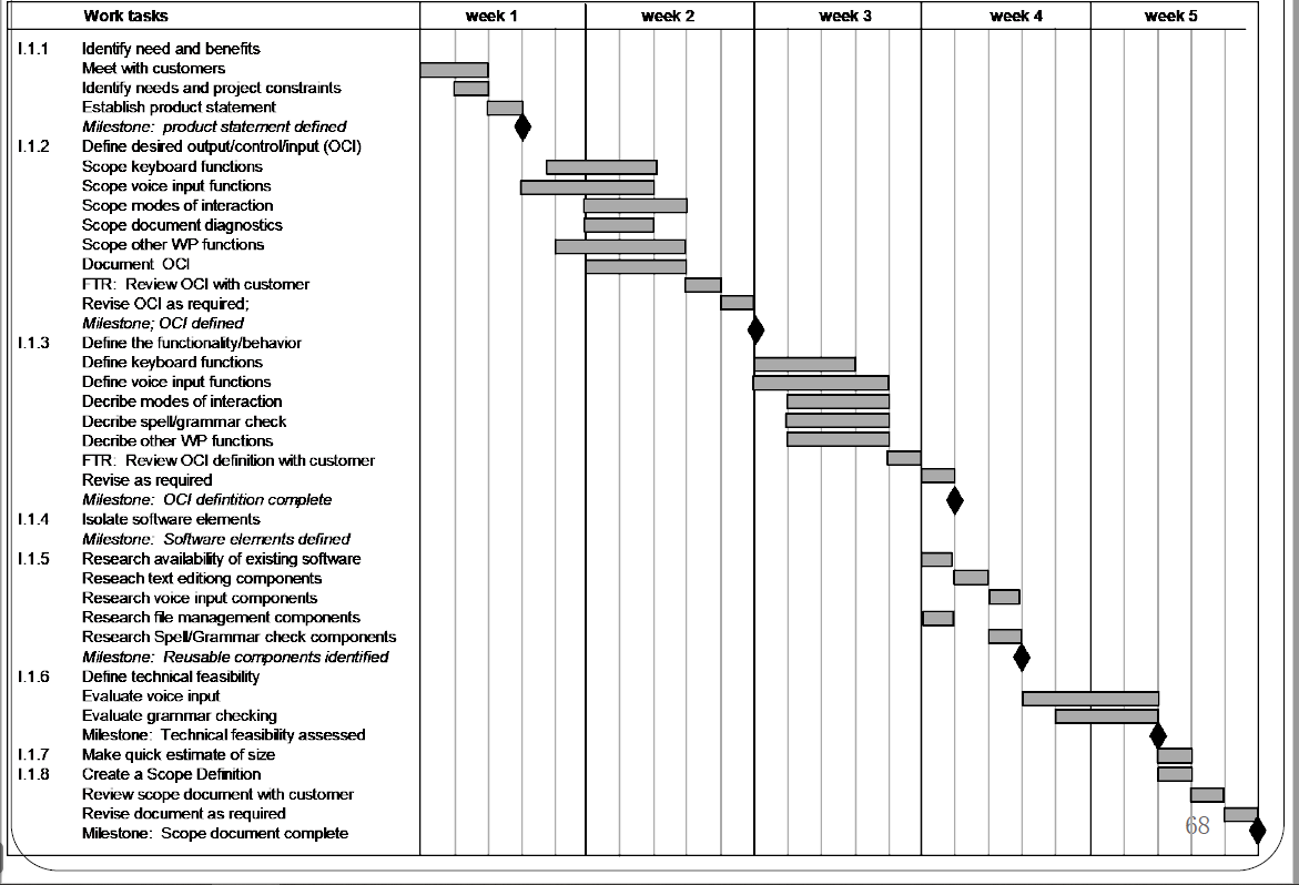
25.5.2 Schedule Tracking
Tracking can be accomplished in a number of different ways:
- conduct periodic project status meetings in which each team member reports progress and problems.定期举行项目状态会议
- evaluate the results of all reviews conducted throughout the software engineering process.
- determine whether formal project milestones (the diamonds shown in Figure) have been accomplished by the scheduled date.
- compare actual start-date to planned start-date for each project task listed in the resource table .
- meet informally with practitioners to obtain their subjective assessment of progress to date and problems on the horizon use earned value analysis to assess progress quantitatively.
Project table
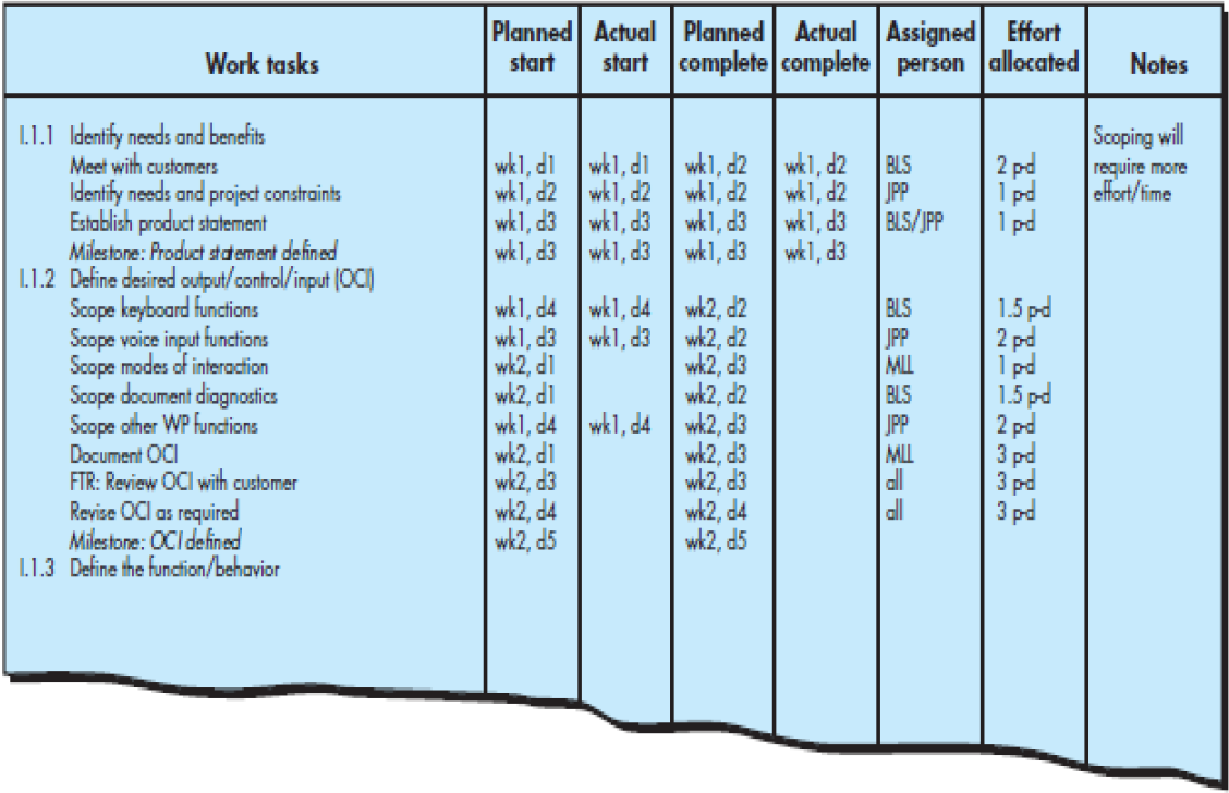
25.6 Earned Value Analysis(EVA)
Earned value用来定量测量项目进展的方法
- is a measure of progress
- enables us to assess the “percent of completeness” of a project using quantitative analysis rather than rely on a gut feeling(直觉).
- “provides accurate and reliable readings of performance from as early as 15 percent into the project.” [Fle98]
Chapter 26 Risk Management
26.1 Concept
A risk is a potential problem—it might happen, it might not.
But regardless of the outcome, it’s a good idea to
- identify it,
- assess its probability of occurrence,
- estimate its impact,
- establish a contingency plan before the problem actually occur.
26.2 Reactive Risk Strategies
A reactive(被动) strategy monitors the project for likely risks.
Resources are not set aside to deal with them until the risk becomes actual problems.More commonly, the software team does nothing about risks until something goes wrong.Then, the team flies into action in an attempt to correct the problem rapidly. This is often called a fire-fighting mode.
When this fails, “crisis management” [Cha92] takes over and the project is in real jeopardy(危险,危机).
26.3 Proactive Risk Strategies
A Proactive risk Strategy is better.It begins long before technical work is initiated.Potential risks are identified, their probability and impact are assessed.The software team establishes a plan for managing risk.The primary objective is to avoid risk, but not all risk can be
avoided.The team works to develop a contingency plan that will enable it to respond in a controlled and effective manner.
26.4 Software Risk
Risk always involve two features:
uncertainty
----the risk may or may not happen.
loss
----if the risk happens, unwanted consequence or losses will occur.
3 Different types of risks are considered.
- Project risk 项目风险
- Technical risk 技术风险
- Business risk 商业风险
26.4.1 Project Risk
Project risks threaten the project plan.
If Project risks become real, it is likely that the project schedule will slip and that costs will increase.Project risks identify potential budgetary, schedule, personnel, resource, stakeholder, and requirements problem and their impact on a software project.
26.4.2 Technical Risk
Technical risk threaten the quality and timelines of the software to be produced.
If a technical risk becomes a reality,implementation may become difficult or impossible.Technical risks identify potential design,implementation, interface, verification, and maintenance problems.
In addition, specification ambiguity, technical uncertainty, technical obsolescence, and “leading-edger technology(前沿技术) are also risk factors.Technical risks occur because the problem is harder to solve than you thought it would be.
26.4.3 Business risk
Business risk threaten the viability of the software to be built and often jeopardize the project or the product.
Candidate for the top 5 business risks are :
(1) Building an excellent product that no one really wants (market risk).
(2) Building a product that no longer fits into the overall business strategy for the company(strategy risk).
(3)Building a product that the sales force doesn’t know how to sell(sales risk).
(4)Losing the support of senior management due to a change in focus or a change in people(management risk).
(5)Losing budgetary or personnel commitment(budget risk).
26.4.4 Seven Principles of Risk Management
Maintain a global perspective
—view software risks within the context of system and the business problem.
Take a forward-looking view
—think about the risks that may arise in the future; establish contingency plans.
Encourage open communication
—if someone states a potential risk, don’t discount it.
Integrate(结合)
—a consideration of risk must be integrated into the software process.
Emphasize a continuous process
—the team must be vigilant throughout the software process, modifying the identified risks as more information is known and adding new ones as better insight is achieved.
Develop a shared product vision
—if all stakeholders share the same vision of the software, it likely that better risk identification and assessment will occur.
Encourage teamwork
—the talents, skills and knowledge of all stakeholder should be pooled.
26.5 Risk Identification
Risk Identification is a systematic attempt to specify threats to the project plan.
26.6 Risk Projection
Risk projection, also called risk estimation, attempts to rate each risk in two ways:
(1) the likelihood or probability that the risk is real
(2) the consequences of the problems associated with the risk, should it occur.
26.7 Risk Mitigation, Monitoring,and Management
An effective strategy for dealing with risk must consider three issues: risk avoidance, risk monitoring, and risk management and contingency planning.
Risk avoidance
—can be achieved by developing a plan for risk mitigation. i.e. figuring out strategies to avoid the risks.
Risk monitoring
—monitor the factors that may provide an indication of whether the risk is becoming more or less likely.
Risk Management and contingency planning
—The risk becomes a reality, we should follow the contingency planning to limit their impact.
Refrence of Northeastern University
R1 Use Case Modeling
R1.1 Unified Process
Unified Process ----a good OO paradigm
Analysis workflow ----to understand requirements deeper, to make it easier to design and implement the target system
Unified process covers 3 kinds of classes:
- Entity class
- Boundary class
- Control class
R1.2 Three Steps of OOA
1.Use-case modeling
- Determine how the various results are computed by the product (without regarding to sequencing)
- Use case diagram
2.Class modeling
- Determine the classes and their attributes
- Class diagram
3.Dynamic modeling
- Determine the actions performed by or to each class
- State diagram
R1.3 What is a Use-Case Model?
- A model that describes a system’s functional requirements in terms of use cases.
- System’s environment ----actors
- System’s intended functions ----use cases
- Relationship between actors and use cases
R2 Use Case Diagram
R2.1 Use-Case Diagram of Elevator Problem
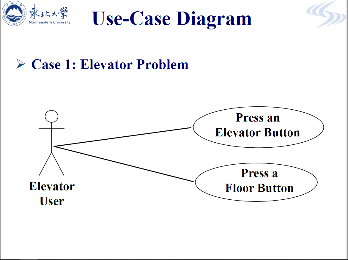
R2.2 Use-Case Diagram of On-line Shop
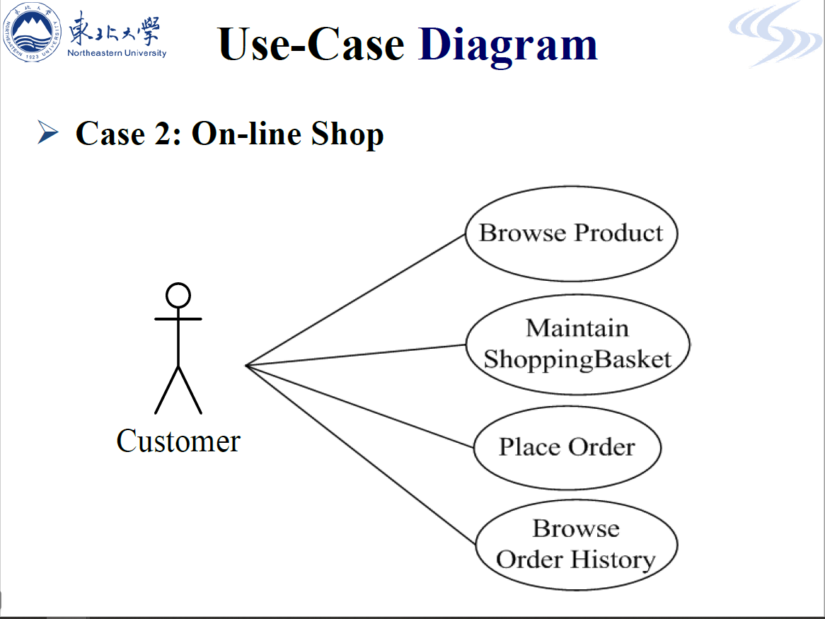
R2.3 Use-Case Diagram of Course Regisration System
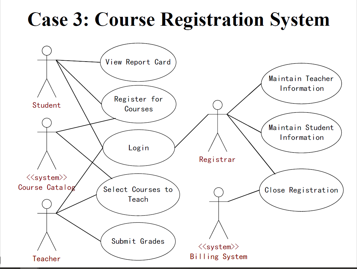
R2.4 Use-Case Specification
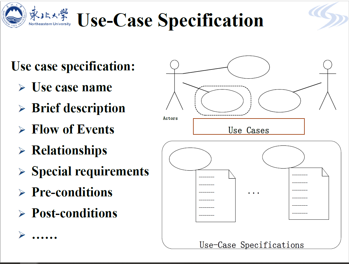
R2.5 The Relationship between Actors(Generalization & Agency)
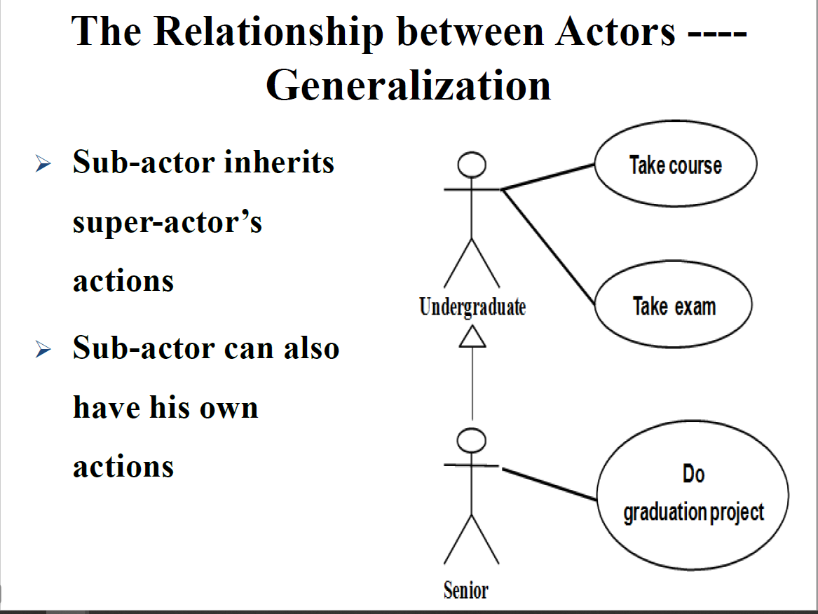
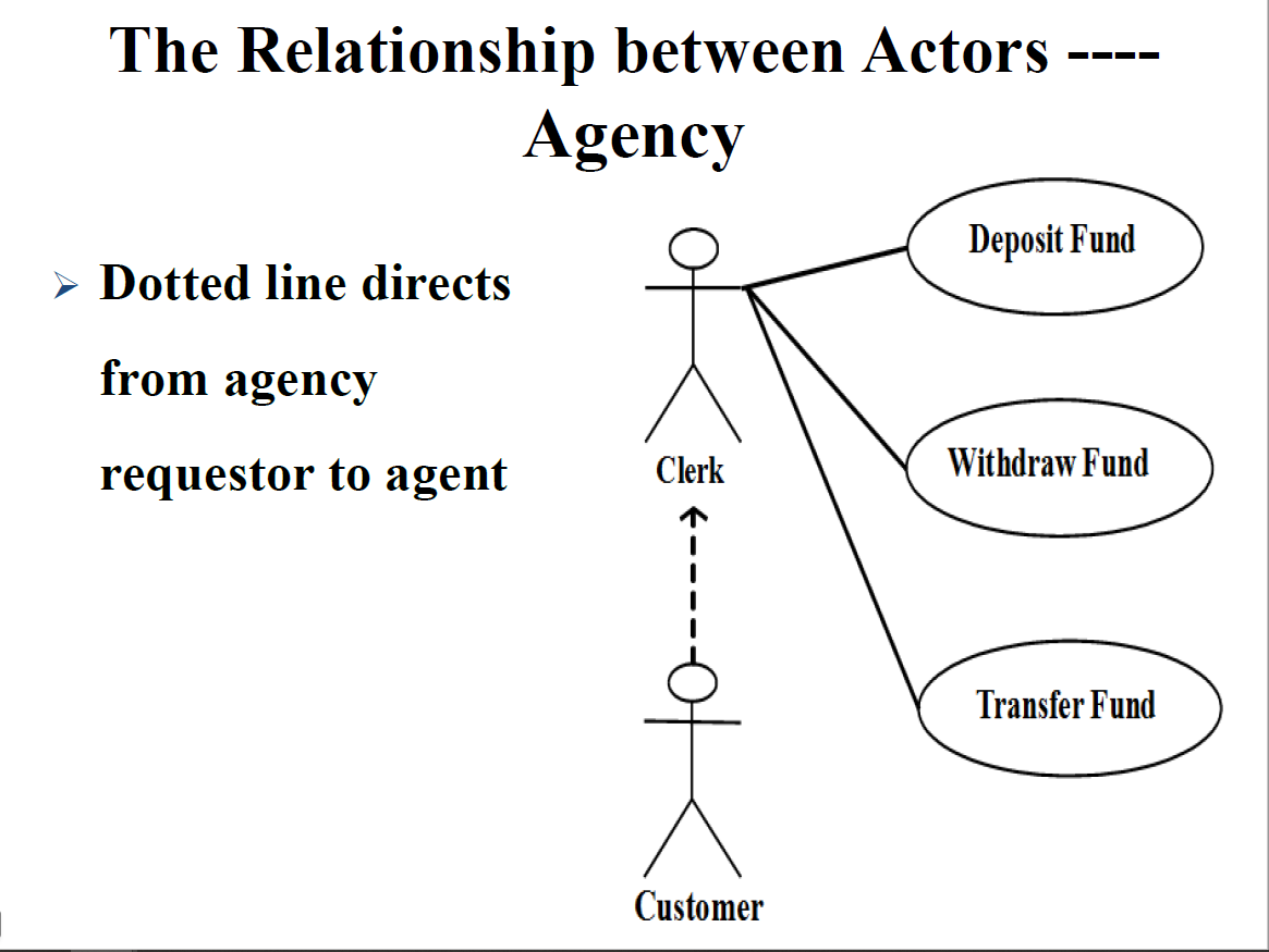
R2.6 The Relationship between use cases(Generalization & Inclusion & Extension)
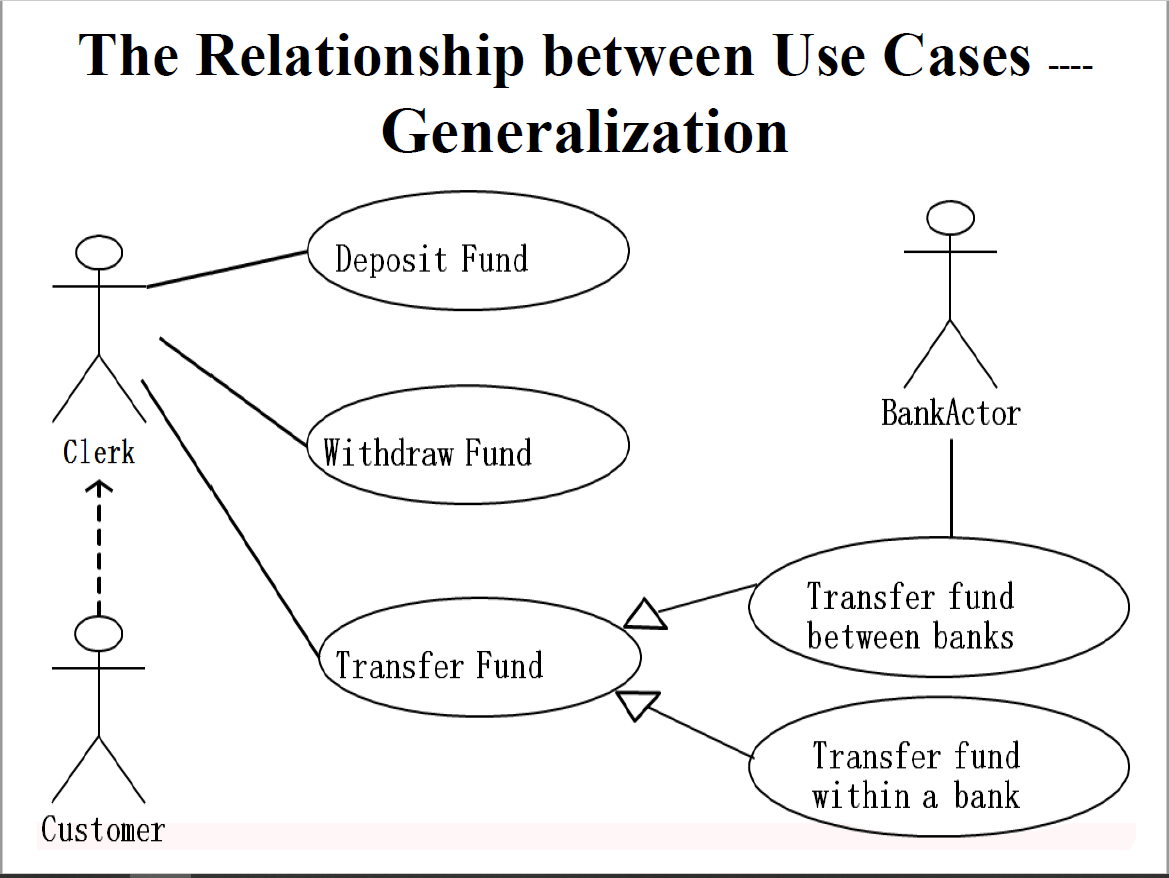
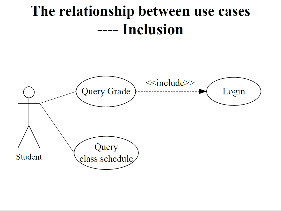
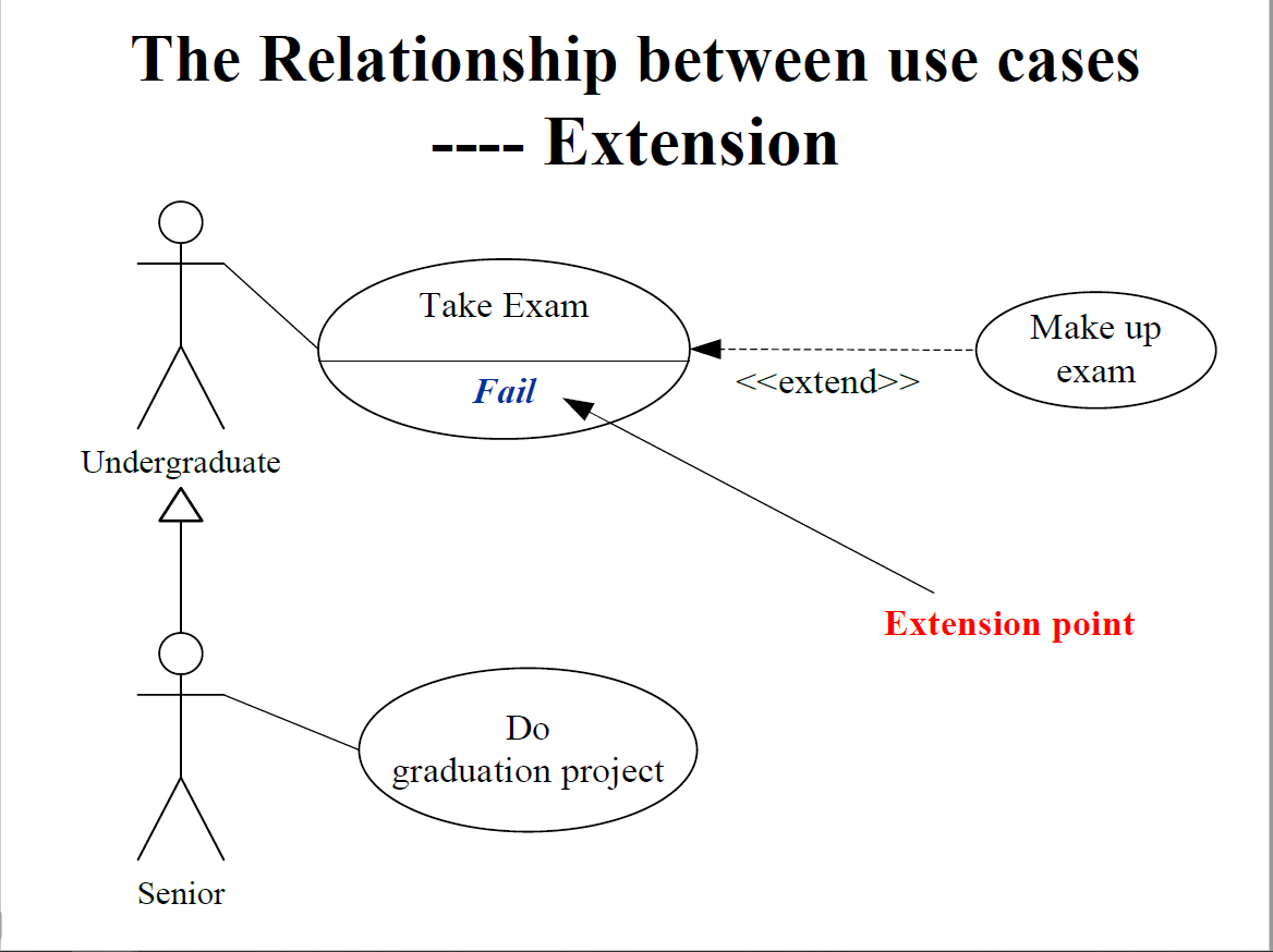
R3 Class Diagram
R3.1 Class Diagram of Elevator
Noun Extraction
Step 1. Concise Problem Definition
- Define product briefly and concisely
Buttons in elevators and on the floors control movement of n elevators in a building with m floors. Buttons illuminate when pressed to request the elevator to stop at a specific floor; illumination is canceled when the request has been satisfied. When an elevator has no requests, it remains at its current floor with its doors closed.
Step 2. Identify nouns
button, elevator, floor, movement, building, illumination, door
- movement, illumination are abstract nouns —exclude (may become attributes)
- floor, building, door are outside problem boundary. —exclude
- Candidate classes: Elevator and ,Button
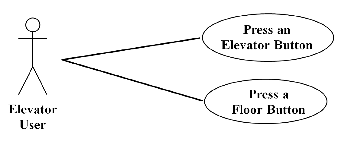
Identify classes from use case diagram: ElevatorButtonand FloorButton
Elevator, Button, ElevatorButton and FloorButton
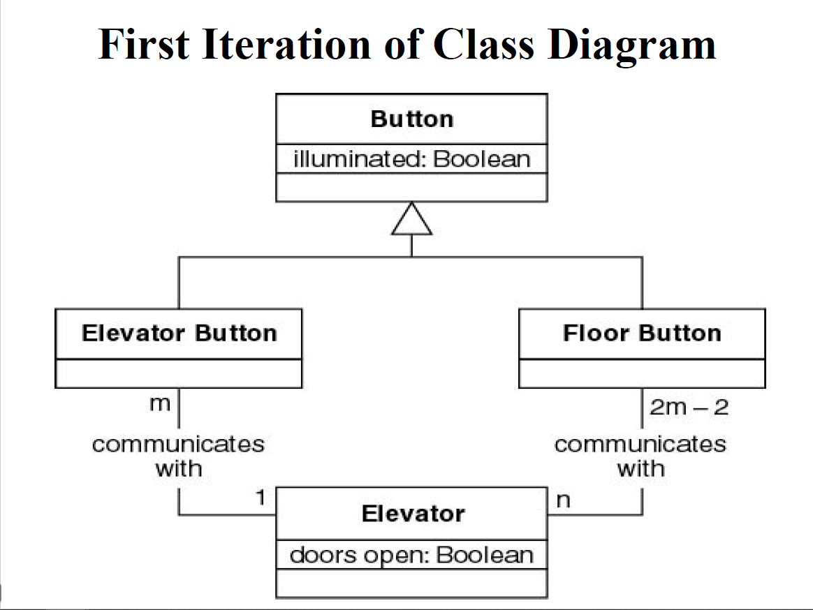
Buttons do not communicate directly with elevators.We need an additional class: ElevatorController
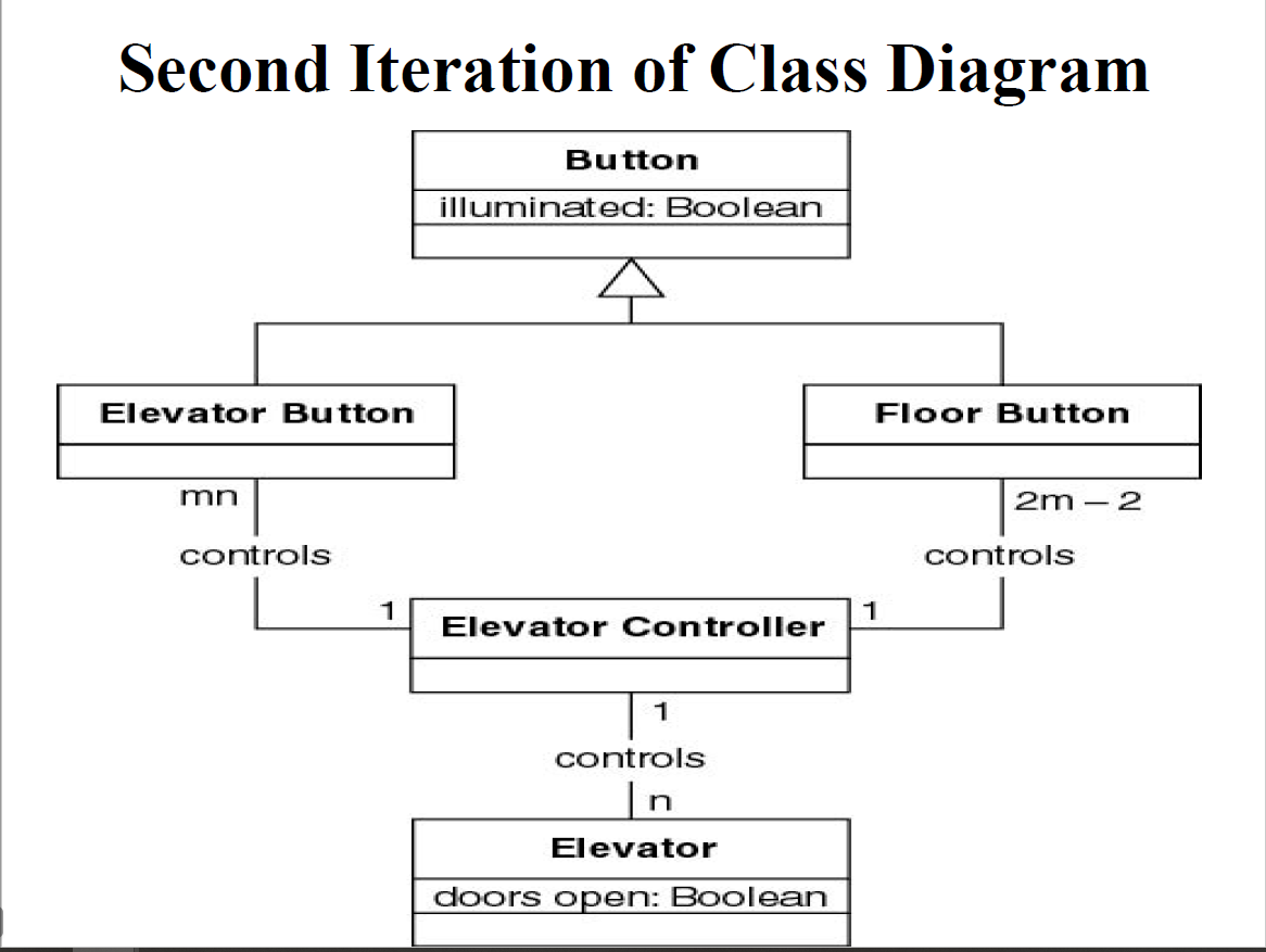
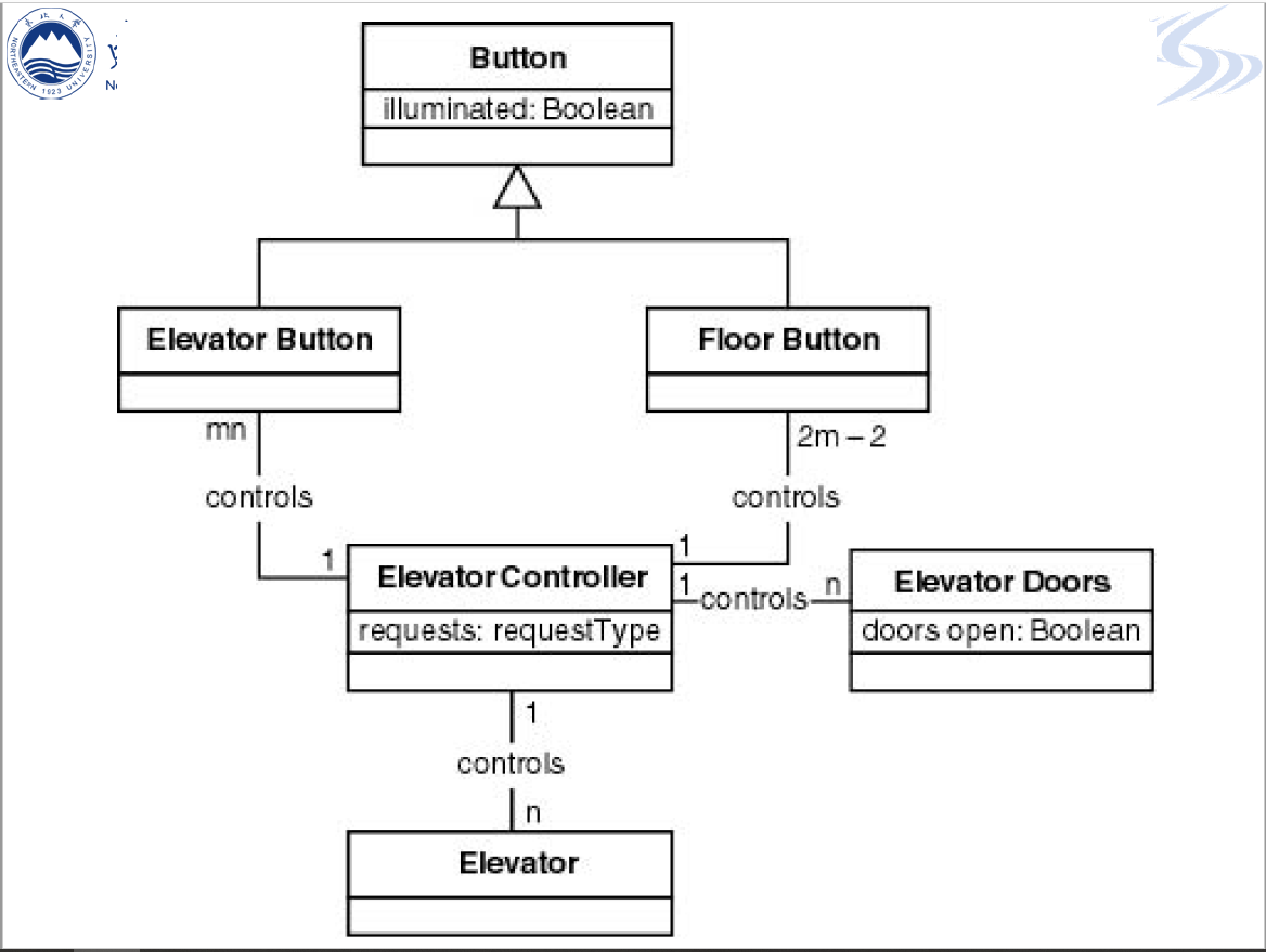
R3.2 Class Diagram of Online Shop
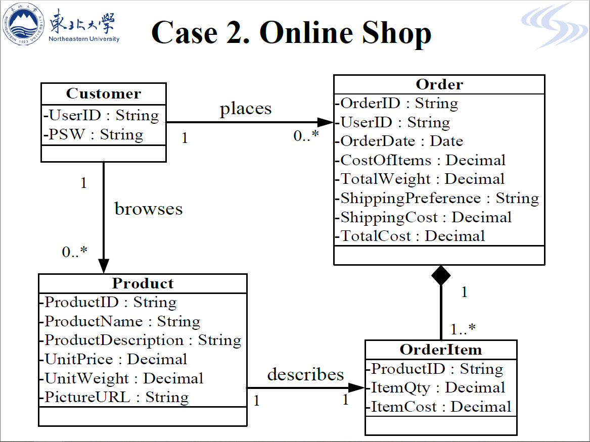
R4 Dynamic Modeling
R4.1 UML state diagram of CD player
Draw a UML state diagram to model the control program for a portable CD player. Include three states: stopped, playing, and paused. Also, include three events possible in any state: pause_is_pressed, stop_is_pressed, and play_is_pressed.
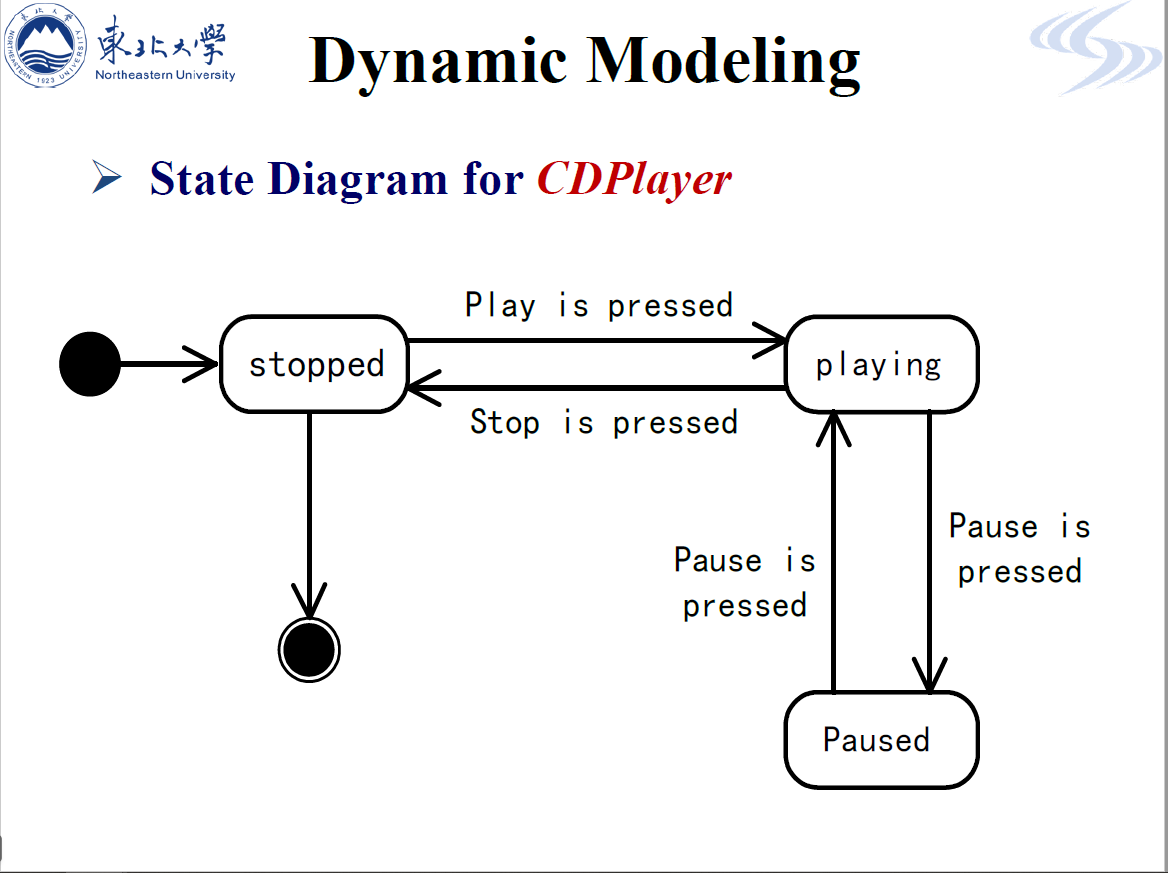
R4.2 UML state diagram of Library Mgmt. System
Draw a UML state diagram for a book in a Library Mgmt. System. Include three states: available, borrowed, and reserved. Also, include events possible in any state: borrow, return, reserve, cancel reservation, reservation times out and renew.
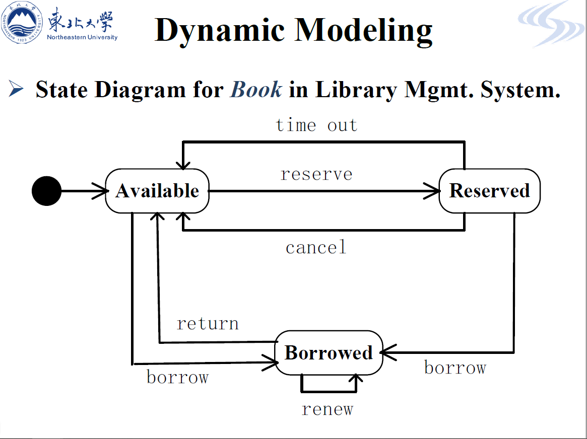
R4.3 UML state diagram of Orderin an eShopsystem
An order goes through the states of placed, paid, shipped, arrived, closed.
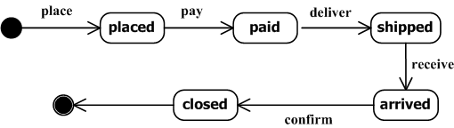
R4.4 UML state diagram of Elevator
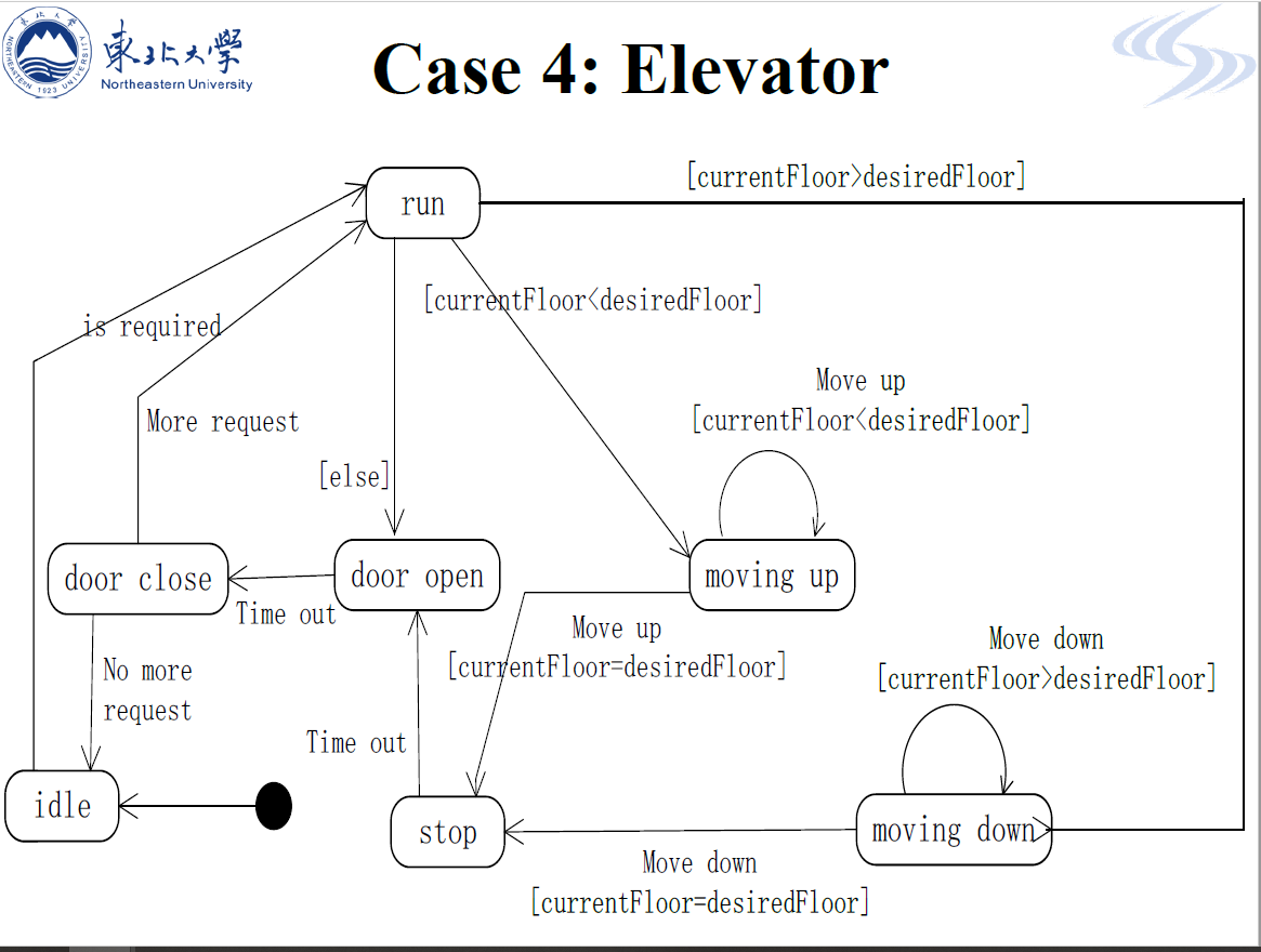
R5 Testing during OOA
R5.1 Elevator
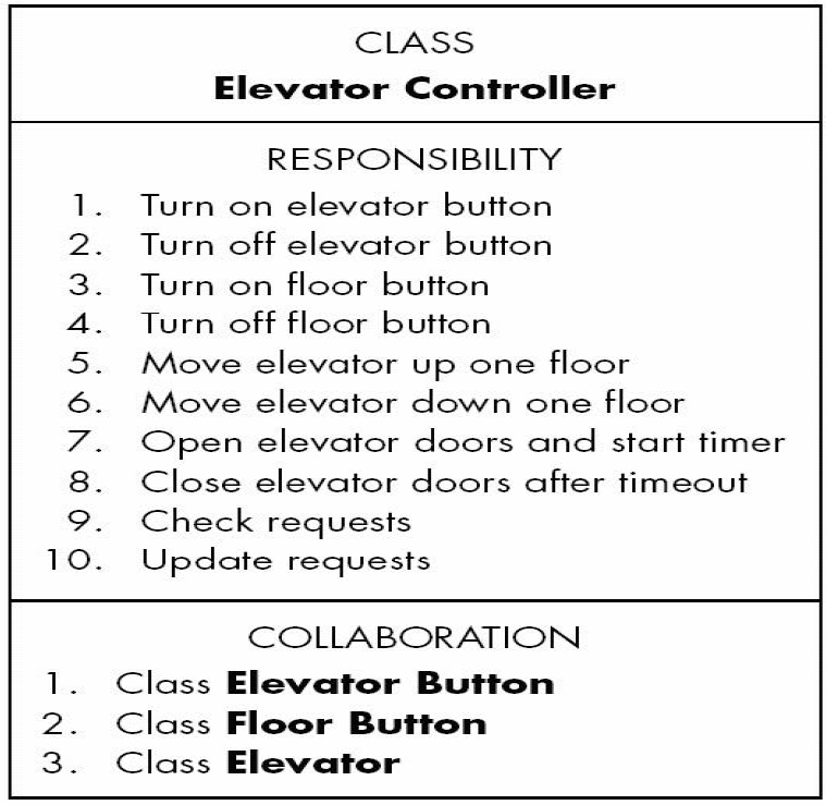
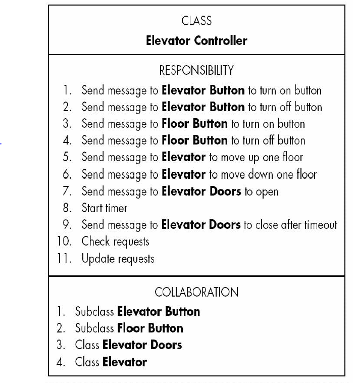
Appendix of abbreviation
A0DL---Architectural Description Language (Chapter 11)
BVA---Boundary Value Analysis (Chapter 18)
CASE---computer-aided software engineering(Chapter 2)
CBD---Computer-Based Development model(Chapter 3)
CRC---Class-responsibility-collaborator model(Chapter 9)
EVA---Earned Value Analysis
FP---Function Point(Chapter 23)
HCI---Human-computer interaction (Chapter 11)
LOC---Lines of code
MOI---MOI model(Leardership Model,Chapter 22)
NATO---North Atlantic Treaty (SE,Chapter 1)
PF---Process framework(Chapter 3)
PNR---Putnam-Norden-Rayleigh Curve(Chapter 25)
QFD---Quality Fucntion Deployment (Chapter 7)
RE---Requirement Engerring
SC---Software Crisis
SE---Software Engineering
SLC---software Life Cycle
SP---Software Process
SPI---Software Process Improvement(Chapter 23)
SQA---Software Quality Assurance(Chapter 16)
SRS---Software Requirements Specification(Chapter 7)
UML---Unified Modeling Language
V&V---Verification & Validation(Chapter 17)
