@TangWill
2019-04-01T01:33:27.000000Z
字数 31611
阅读 2389
Final Report Of Computer Organization Principle
SE
- Final Report Of Computer Organization Principle
- Abstract
- 1. The ideas of stored program "Von Neumann" computer
- 2. The computer internal data representation
- 3. The arithmetic operation process
- 4. Instruction, instruction set, ISA, code, application
- 5. Instruction, operation, clock cycles
- 6. Instruction and data memory addressing methods
- 7. Storage system features and the basic idea of memory extensions
- 8. Input and output system
- 9. Understanding and conclusion
Abstract
After studying the principle of computer composition for 16 weeks, I have a preliminary understanding and understanding of the hardware composition of the computer and the program storage and operation inside the computer, and have a deeper and more comprehensive understanding and understanding of the programming knowledge and computer basic knowledge required before.
In this article, I will sort out and explain the notes and understanding of the 16 - week study according to my sorting out of the curriculum structure and context, and introduce some knowledge concepts from textbooks and handouts. This article focuses on my own understanding and mastery of curriculum knowledge. If you have any shortcomings, please correct them.
1. The ideas of stored program "Von Neumann" computer
According to Von Neumann's idea of the five functional components of a computer, a computer includes five functional components such as an input device ( I ), an arithmetic unit ( ALU ), a controller ( CU ), a memory ( M ) and an output device ( O ).
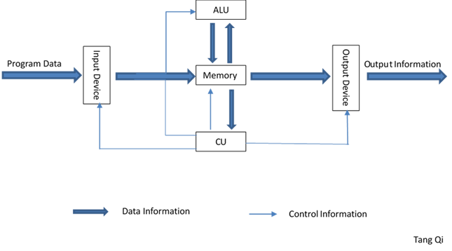
According to Von Neumann's original idea of computer, the concept of stored program is the basic premise of computer automation. That is to say, if you want to use a computer to complete a task, you must describe the task in some language and write the corresponding program. In short, a program is a sequence of instructions, while an instruction is the definition and description of a relatively independent task performed by a computer hardware system.
The basic process of executing an instruction can be described as follows:
1. Take this instruction from main memory and put it into CPU ( special register, etc. );
2. The CPU analyzes this instruction to form corresponding timing and control signals;
3. If the operand is in main memory, fetch the operand to CPU;
4. If necessary, the CPU performs operations;
5. If necessary, store the results in main memory.
The host should be the minimum configuration that the system can solve the problem regardless of input and output. Therefore, what is commonly called a host includes two basic components: CPU and main memory.
The external equipment is responsible for information exchange with the host's external environment. The so-called input devices refer to the devices that transmit information to the host. They are the means by which the host obtains external information. The so-called output devices are all devices that receive information about the host, and they are the means by which the host sends data to the outside.
With the development of modern computer technology, multi-level storage system has become one of the main technologies supporting modern computers. The division of memory functions is the primary task of a multi-level storage system. Among them, the function division between memory and external memory is the most basic work. Since the main function of external storage is to send and receive data to and from the host, and special interfaces are needed to deal with the host, external storage should belong to peripherals.
The main task of the CPU is to execute programs stored in the computer. From a functional point of view, the CPU is the control center of all components, that is, the CPU controls the corresponding functional components to work together through the interpretation and execution of programs. In terms of basic structure, he is actually the general name of the controller and arithmetic unit envisaged by Von Neumann.
Modern computer is a multi-level storage system, among which cache, main memory and external memory are the most common three-level storage architectures. Cache is a small but fast memory located between CPU and main memory. He raised and developed the problem that CPU speed is much higher than main memory access speed, the purpose of which is to solve the problem of speed difference between CPU and main memory data access.
A computer hardware system needs not only the necessary functional components, but also the corresponding components such as CPU, main memory and peripherals. At present, computers are mainly connected by bus technology.
Bus is a group of public information transmission lines.Bus is generally divided into DB, AB and CB. DB is used to transmit data information. The data bus is bidirectional. It can transfer CPU data to main memory or I/O interface, or their data or instructions to CPU. AB is specially used to transfer addresses, mainly instruction addresses, main memory addresses corresponding to operands, or peripheral addresses. AB is unidirectional. CB is used to transmit control signals.
2. The computer internal data representation
Data information is the object of computer processing and processing. The representation of data information will directly affect the structure and performance of the computer. Data representation refers to data types directly identified by computer hardware, such as fixed point numbers, floating point numbers, etc.
In computers, binary numbers consisting of only two basic symbols of " 0" and " 1" are widely used instead of the usual decimal numbers for the following reasons:
- Binary numbers are physically the easiest to implement. For example, only the high and low levels can be used to indicate " 1" and " 0", or the presence or absence of pulses or the positive and negative polarities of pulses can be used to indicate them.
- The rules of encoding, counting, adding and subtracting binary numbers are simple.
- The two symbols " 1" and " 0" of the binary number correspond exactly to the two values " yes" and " no" or " true" and " false" of the logical proposition, providing a convenient condition for the computer to realize logical judgment.
2.1 Counting System and Interconversion
Among them, is the basic symbol used in the digital system, and can take 0, 1, 2, ..., r-1, with the decimal point between and .R is the base number, i is the bit sequence number, is the number, is the weight of the corresponding bit, represents the actual value on bit i .
2.2 Machine number representation method
The method of representing a binary number in a computer is called numerical coding, and the representation of a number and its symbols in a machine is digitized, called machine number. The number represented by the number of machines is called the true value of the number.
In arithmetic operations, data are positive and negative, and this kind of data is changed into signed numbers. Generally, the highest bit of each word length is defined as the sign bit, with 0 representing a positive number and 1 representing a negative number.
The number of machines where the decimal point position is fixed is called fixed point number, and the number of machines where the decimal point position can float is called floating point number.
True Form
The sign bit of positive number is 0, the sign bit of negative number is 1, and the other bits represent the absolute value of the number in the usual way. In this way, the original code of the number is obtained.
Two's Complement
Positive numbers have the same form of original code and complement code; When the negative original code is converted to its complement, the sign bit remains "1" and the rest of the bits are inverted, adding 1 to the last bit.
One's Complement
The negative number of a positive number is the same as its original code; The negative counter-code reverses its original code bit by bit, except for the sign bit.
Frameshift
The Frameshift is a complement to the inverse of the sign bit and is generally used as the order code of floating point numbers. The purpose of the introduction is to ensure that the machine zero of floating point numbers is all zero.
The highest bit of the shift code is the symbol bit, representing the opposite form of the original code and complement, with 1 representing positive and 0 representing negative.
2.3 Number Range
Fixed-point integer
Ture form
Two's Complement
Fixed-point Decimal
True form
Two’s complement
Float Point
| Sign | Exponent | Mantissa |
|---|
The exponent is a signed integer in the machine and is generally expressed as a frameshift or two's complement code. The mantissa is a pure decimal, usually expressed in the true form or two's complement, and the sign bit is the sign bit of the mantissa, usually arranged in the highest bit, representing the positive and negative of the whole floating point number.
The representation range of floating point numbers in computers is mainly defined by exponent, and the accuracy is mainly determined by mantissas. In order to improve the accuracy of the operation, the effective number of mantissas should occupy as many digits as possible, and at the same time, the computer should have a uniform and fixed standard format when implementing floating-point operations, so that floating-point data can be expressed in a normalized form. The limitation range of floating point number normalization to mantissa is:
If the effective number of mantissa in floating-point operation exceeds most significant bit, it needs to be right - normalized. If the effective number of mantissa in operation is not in most significant bit, it needs to be right - normalized.
if l indicates the amount of exponent digits and n indicates the amount of mantissa digits,
IEEE 754
According to the standard, the base number is 2, the order code is represented by the deformed shift code, and the mantissa is represented by the original code. In order to make the mantissa part have one more valid value, the standard adopts the method of hiding the highest bit of mantissa 1. The range of order code representation changed from - 126 to 127 to 1 to 254.
3. The arithmetic operation process
Fixed-point
ADD:
SUB:
MULT:
Float-point
ADD and SUB
Assume
(1) Match exponent
① Calculate exponent difference △E = Ex - Ey
If △E=0,no need to match. Otherwise, need to change exponent according to |△E|.
② Reserve big exponent
③ Mantissa with small exponent shifts right until △E=0, with exponent plus one each shift.
(2) Calculate sum or difference
(3) Normalization
① Left Normalization
Condition: the sign bit of mantissa is same as MSB.
Method: mantissa shift left until the sign bit is not same as MSB, with exponent minus one each shift.
② Right Normalization
Condition: the two sign bits is not same.
Method: mantissa shift right one bit and exponent plus one.
(4) Rounding
MULT
Assume
4. Instruction, instruction set, ISA, code, application
A computer program is made up of machine instructions. Machine instructions are the only language a computer can recognize. A machine instruction is a combination of 0 and 1 codes represented in binary bits. According to different combinations of 0 and 1 codes, the hardware controlling the machine performs different operations to realize different functions of the machine.
The set of machine instructions that implement various functions in a computer is called the machine's instruction system.
In this report, I will take MIPS as an example to continue to explain this part.
MIPS instruction system adopts 32 - bit equal-length instruction format and has three types of instruction formats: R - Format, I - Format and J - Fromat.
R-Fromat
| OP | rs | rt | rd | shamt | funct |
|---|
| 6 | 5 | 5 | 5 | 5 | 6 |
|---|
I-Fromat
| OP | rs | rt | imm |
|---|
| 6 | 5 | 5 | 16 |
|---|
J-Fromat
| OP | taraddr |
|---|
| 6 | 26 |
|---|
The meaning of each field is as follows:
OP: 6 - bit operation code, indicating the basic operation of the instruction
rs:5 - bit source operand register address
rt:5 - bit source operand or destination operand register address
rd:5 - bit destination operand register address
shamt:5 bits of displacement
function: 6 - bit auxiliary operation code
imm: 16 - bit constant
taraddr: 26 - bit target address
Arithmetic / logic operation instructions generally adopt R - Format instruction; Instructions such as immediate, data transfer and branch are in type I -Format instruction. Jump class instruction adopts J - Format instruction.
For example
add $1,$2,$3
Field representation (decimal):
| 0 | 2 | 3 | 1 | 0 | 32 |
|---|
Field representation (binary):
| 000000 | 00001 | 00010 | 00000 | 00000 | 100000 |
|---|
addi $1,$2,-50
Field representation (decimal):
| 8 | 2 | 1 | -50 |
|---|
Field representation (binary):
| 001000 | 00001 | 00000 | 1111111111001110 |
|---|
There is a samll program to help me explain the instructions of MIPS.
main:ori $t1,$0,2ori $t2,$0,1addu $t3,$t1,$t2ori $t4,$0,5subu $t5,$t4,$t1here:beq $t1,$t2,jheresw $t1,4($0)j endjhere:ori $t2,$0,2j stopend:lw $t6,4($0)lui $t7,100ori $t1,$0,1j herestop:
Assume a, b, c are stored in s1, s2, s3 attributely.
a=b+c;
add $s1,$s2,$s3
a=b-c;
sub $s1,$s2,$s3
c=a+5;
c++;
addi $s3,$s1,5addi $s3,$s3,1
In the MIPS,MIPS has 32 registers and each register is 32 bits wide and hold a word.
Register denoted by '$' can be referenced by number ($0-$31) or name:
Registers that hold programmer variables: $s0-$s7 or $16-$23
Registers that hold temporary variables: $t0-$t7 or $8-$15 and $t8-$t9 or $24-$25.
In these registers,one of them is special. It's zero register.Register zero($0 or $zero)always has the value 0 and cannot be changed.
As we all know,there are 32 bits per instruction of MIPS.Hence,how to deal with the big number or array?We can store them into main memory and then take it into the register when it is needed.It's meant that we need some instructions to help us load or save some large data.
address of int A[]->$s3, a->$s0
lw $t0,12($s3) #st0=A[3]add $t0,$s0,$t0 #$t0=A[3]+asw $t0,40($s3) #A[10]=A[3]+a
Notice that the number before the register or basic address are times of 4,which is called word-aligned.
if (a == b)
……
else
beq $s1,$s2,labelj label1……
If calue in first register eaquals to value in second register,the pc will go to label.Label is defined by text folowed by a colon(e.g. main:) and refers to the instruction that follows.However,if the value in two registers are not eaqual,we need another instruction—J.
if (i == j) a = b;
else a = -b;
beq $1,$2,mainsub $3,$0,$4j cotinuemain:add $3,$0,$4continue:……
If we want to load a constant into the upper half of a word,it's nessary to ues instruction——lui.This instruction moves 16-bit into upper half of register and zeros the lower half.
addi $t0,$t0,0xABABCDCD
lui $at 0xABAB #upper 16ori $at $at,0xCDCD #lower 16add $t0,$t0,$at #move
5. Instruction, operation, clock cycles
The operation of the computer is to make the machine continuously fetch an instruction from main memory and execute it under the control of the CPU. Then take down a command and execute it. This is repeated until the shutdown command is executed. The process of executing an instruction by a machine is usually divided into several different stages and the execution of the instruction is completed with corresponding pulses.
Under the control of the CPU, the time required for the machine to access an instruction from the master and execute the instruction is called the instruction cycle. Due to the different functions implemented by the various instructions, the execution time of the various instructions in the instruction system is different, that is, the instruction cycles of the various instructions are different.
In an instruction cycle, the time period for completing different tasks is called the corresponding machine cycle. In general, the time required to fetch an instruction from main memory to the CPU is called the instruction fetching machine cycle. The time required to fetch operands is called the fetch operand machine cycle. The time required to operate an instruction and write a result to a destination is called the execution machine cycle.
The clock pulse signal is the basic timing signal that controls the operation of the machine. Generally, the clock pulse signal CLK is generated by the quartz crystal oscillator. The rising edge of the clock pulse signal can be used to drive the data somewhere. The falling edge of the clock pulse signal is used to save the data operation result.
Execution Cycle
1. Instruction Fetch
2. Instruction Decode
3. Execute
4. Memory
5. Write Back
Firstly,CPU needs to fetch a instruction from the main memory and then increase the value of program counter by 4.
Secondly, figure out what the instruction says to do and get values from the named registers. Simple instruction format means we know which registers we may need before the instruction is fully decoded. Just I mentioned before,there are three fomats of instruction, which are R-Format, I-Format and J-Format. According to the opcode of each instruction(highest six-bit), controller can indentify the type or format of the instruction feched from the IM. Besides,if the instruction is a R-Format instruction, the founc code is necessary(lowest six-bit), which will help controller to know the funciton of the instruction.
Next,on a memory reference, add up base and offset or on an arithmetic instruction, do the math.And what we should know is that if load or store, access memory and if branch, replace PC with destination address.Otherwise do nothing.
Finally,place the results in the appropriate register.
The most important thing is that controller will determine the value of the signals according to the opcode and founc code,which will be used to select inputs and operations.
Let's take some examples:
ADD
add $s0, $s1, $s2
IF get instruction at PC from memory
| 000000 | 10001 | 10010 | 10000 | 00000 | 100000 |
|---|
ID determine what instruction is and read registers
- 000000 with 100000 is the add instruction
- get contents of $s1 and $s2 (eg: $s1=7,$s2=12)
EX add 7 and 12 = 19
MEM do nothing for this instruction
WB store 19 in register $s0
lw
lw $t2, 16($s0)
IF get instruction at PC from memory
| 010111 | 10000 | 01000 | 0000000000010000 |
|---|
ID determine what 010111 is
- 010111 is lw
- get contents of $s0 and $t2 (we don’t know that we don’t care about $t2) $s0=0x200D1C00, $t2=77763
EX add 16 to 0x200D1C00 = 0x200D1C10
MEM load the word stored at 0x200D1C10
WB store loaded value in $t2
Last but not least, I want to show the value of the signals in different instructions.
| 10 0000 | 10 0010 | n/a | n/a | n/a | n/a | n/a | n/a | |
|---|---|---|---|---|---|---|---|---|
| 000000 | 000000 | 001101 | 100011 | 101011 | 000100 | 000010 | 001111 | |
| add | sub | ori | lw | sw | beq | j | lui | |
| RegDst | 1 | 1 | 0 | 0 | x | x | x | 0 |
| ALUSrc | 0 | 0 | 1 | 1 | 1 | 1 | 0 | 0 |
| MemtoReg | 0 | 0 | 0 | 1 | x | x | x | 0 |
| RegWrite | 1 | 1 | 1 | 1 | 0 | 0 | 0 | 1 |
| MemWrite | 0 | 0 | 0 | 0 | 1 | 0 | 0 | 0 |
| nPC_sel | 0 | 0 | 0 | 0 | 0 | 1 | 0 | 0 |
| ExtOp | x | x | 0 | 1 | 1 | x | x | 0 |
| ALUctr<1:0> | 00 | 01 | 10 | 00 | 00 | 01 | x | 11 |
| JumpCtr | 0 | 0 | 0 | 0 | 0 | 0 | 1 | 0 |
These signals' function just as following picture shows.
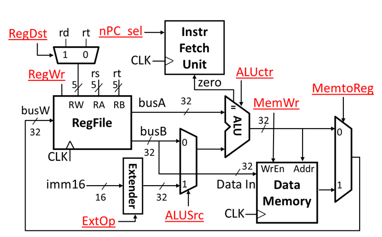
It should be noted that ExtOp is used to judge the symbol expansion and zero expansion. Npc_sel needs to judge whether the two values are equal or not together with zero. When npc_sel is zero, the current instruction is beq, and when zero is zero, the two values are equal.
6. Instruction and data memory addressing methods
The address of an operand or instruction in memory: the number of its memory location when an operand or instruction is stored in a memory location.
In memory, there are three ways to write or read operands or instructions: address designation, associative storage and stack storage.
When the address designation mode is adopted, the mode of forming operand or instruction addresses is called addressing mode. There are two types of addressing modes, namely, instruction addressing mode and data addressing mode.
There are two ways of addressing instructions, one is sequential addressing and the other is skip addressing.
The addressing mode of the instruction
(1) Sequential addressing mode
Instruction addresses are arranged sequentially in memory. When a program is executed, it is usually executed one instruction after another.
To do this, a program counter ( also called instruction pointer register ) PC must be used to count the sequence number of the instruction, which is the address of the instruction in memory.
(2) Jump addressing mode
When the program shifts the order of execution, the instruction is addressed in a jump addressing mode. The so-called jump means that the address code of the next instruction is not given by the program counter, but by this instruction. After the program jumps, it starts to execute in the order of the new instruction address.
Operand addressing mode
The so-called addressing method of operands is the method of forming effective addresses of operands.
For example, the structure of a single-address instruction is shown below, where the operand address of the instruction is composed of x, I, and d fields.
The address code of the operation number segment in the instruction is formed by the combination of formal address and address mode characteristic bit, so in general, the address code given in the instruction is not the effective address of the operand. Therefore, the addressing process is the process of transforming the formal address of the operand into the effective address of the operand.
(1) Implicit addressing
The address of the operand is not explicitly given in the instruction but is implied. For example, the instruction format of a single address does not specify the second operand address in the address field, but specifies the accumulation register AC as the second operand address, and AC is an implicit address for the instruction format of a single address.
(2) Immediate addressing
The address field of the instruction indicates not the address of the operand, but the operand itself. This method is characterized by short instruction execution time and does not need to access memory to retrieve data.
For example, the shift instruction format for a single address is OP ( shift ) f d
D here is not an address, but an operand. F is the flag bit. When F = 1, the operand moves to the right. When f = 0, the operand moves to the left.
Direct addressing: is a basic addressing method, which is characterized in that the address d where the operand is in memory is directly indicated in the address field of the instruction format.
When the direct addressing mode is adopted, the formal address d in the instruction word is the effective address e of the operand, i.e. e = D. Therefore, the formal address D is also commonly referred to as a direct address. At this point, the indication is given by the addressing mode. If the operand is represented by s, the logical expression directly addressed is
Indirect addressing: Compared with direct addressing, in the case of indirect addressing, the formal address D in the instruction address field is not the real address of the operand, but an indicator of the address of the operand, or the content of the D unit is the effective address of the operand.
The addressing characteristic bit I = 0 indicates direct addressing, at which time the effective address E = D; I = 1, which means indirect addressing, when the effective address e = ( d ).
Indirect addressing was often used in early computers, but it is no longer used because it affects the execution speed of instructions due to two memory accesses.
Register addressing mode and register indirect addressing mode: register addressing mode can be adopted when operands are not placed in memory but in general registers of CPU.
The operand address is not the address unit number of the memory, but the number of the general register.
The difference between the register addressing mode and the register indirect addressing mode is that the register content in the instruction is not an operand, but an address of the operand, and the operand indicated by the address is in memory.
Relative addressing: The content of the program counter PC is added to the formal address D in the instruction format to form the effective address of the operand.
The content of the program counter is the address of the current instruction. " Relative" addressing is relative to the current instruction address.
The advantage of using relative addressing is that programmers do not need to program with absolute addresses of instructions, and programs can be stored anywhere in memory. At this time, formal address D is usually called offset, and its value can be positive or negative, floating relative to the current instruction address.
Base Address: Add the contents of the base address register in the CPU to the formal address in the instruction format to form the effective address of the operand.
Its advantage is that it can expand the addressing capability. Compared with the formal address, the number of bits of the base address register can be set to be very long so that it can be addressed in a larger memory space.
7. Storage system features and the basic idea of memory extensions
Memory can be classified into random access memory, read-only memory, sequential access memory and direct access memory.
7.1 Static RAM
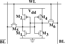
Figure shows the structure of a 6 transistor SRAM cell. The core of this cell is formed by the four transistorsM1toM4which form two cross-coupled inverters. They have two stable states, representing 0 and 1 respectively. The state is stable as long as power onVddis available.
If access to the state of the cell is needed the word access lineWLis raised. This makes the state of the cell immediately available for reading onBLandBL. If the cell state must be overwritten theBLandBLlines are first set to the desired values and thenWLis raised. Since the outside drivers are stronger than the four transistors (M1throughM4) this allows the old state to be overwritten.
For the following discussion it is important to note that
- one cell requires six transistors. There are variants with four transistors but they have disadvantages.
- maintaining the state of the cell requires constant power.
- the cell state is available for reading almost immediately once the word access lineWLis raised. The signal is as rectangular (changing quickly between the two binary states) as other transistor-controlled signals.
- the cell state is stable, no refresh cycles are needed.
There are other, slower and less power-hungry, SRAM forms available, but those are not of interest here since we are looking at fast RAM. These slow variants are mainly interesting because they can be more easily used in a system than dynamic RAM because of their simpler interface.
7.2 Dynamic RAM
Dynamic RAM is, in its structure, much simpler than static RAM. Figure shows the structure of a usual DRAM cell design. All it consists of is one transistor and one capacitor. This huge difference in complexity of course means that it functions very differently than static RAM.
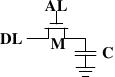
A dynamic RAM cell keeps its state in the capacitorC. The transistorMis used to guard the access to the state. To read the state of the cell the access lineALis raised; this either causes a current to flow on the data lineDLor not, depending on the charge in the capacitor. To write to the cell the data lineDLis appropriately set and thenALis raised for a time long enough to charge or drain the capacitor.
There are a number of complications with the design of dynamic RAM. The use of a capacitor means that reading the cell discharges the capacitor. The procedure cannot be repeated indefinitely, the capacitor must be recharged at some point. Even worse, to accommodate the huge number of cells (chips with 109 or more cells are now common) the capacity to the capacitor must be low (in the femto-farad range or lower). A fully charged capacitor holds a few 10's of thousands of electrons. Even though the resistance of the capacitor is high (a couple of tera-ohms) it only takes a short time for the capacity to dissipate. This problem is called “leakage”.
All storage capacitors are recharged every 2ms,which is called refresh. DRAM need to refresh each 2ms or random time. Centralized Refresh、Scattered Refresh and Asynchronous Refresh.
7.3 memory extensions
Bit Expansion
The data is joining together and sharing
Word Expansion
High addresses are decoded to produce several different chip select signals,according to each chip in the storage space distribution. Low addresses are decoded to select directly a certain cell in the chip.
8. Input and output system
Input Output System is the management of information exchange between host and peripherals and among peripherals.
The basic function of the input / output system is to manage the exchange of information between the host computer and peripherals and peripherals. Hardware and software complete this task together. The basic principle is not to lose data. Fast exchange of data, low cost, host and peripherals, peripherals and peripherals work in parallel as much as possible to give full play to their potential.
There are typical control modes of information transmission between the host and peripherals.
- Programmed Direct Control
The direct control mode of the program is that the program controls the data exchange between the host computer and the peripheral equipment.
Program Interrupt
After the host starts the peripheral, the CPU continues to execute the original program. When the peripheral is ready for input / output, it sends an interrupt request to the host. After the host receives the request, it temporarily suspends the original program, turns to execute the interrupt service program to process the external request, and returns to the original program to continue execution after the interrupt processing is completed.Direct Memory Access (DMA)
Direct memory access is a way of transferring data between main memory and I/O devices directly by hardware. CPU is not required to participate in the transfer operation during the transfer. DMA mode is a way to open up a " direct data channel" between peripherals and main memory, and make high-speed data transfer between them without CPU intervention or software intervention.Channels Mode
The channel control mode is a further development of DMA mode. The system is equipped with channel control components, each channel has several peripherals. When the host performs I/O operations, it only needs to start the relevant channels, and the channels will execute the channel program, thus completing the I/O operations.
9. Understanding and conclusion
I studied the course "Computer Organization Principle "for a semester. After the teacher taught us the course "Principles of Computer Composition", we all have a deeper understanding and understanding of computers. Computer technology is one of the fastest growing science and technology in the world, and products are constantly upgraded. At present, the computer is developing in the direction of megalopolization, miniaturization, intelligence and networking. The performance of the computer itself is becoming more and more superior and its application scope is becoming wider and wider, thus making the computer an indispensable tool in work, study and life. We are only a small explorer of computers, and there is a larger ocean of knowledge waiting for us to dig and learn.
At the beginning of this semester, we studied the course " Principles of Computer Composition" from a shallow to a deep level in the teacher's lecture. Starting from the introduction of computer in the first chapter, the development, classification and application of computer are described. The working process and performance index of the computer; The basic composition of the computer system; The hierarchy of computer systems. Then we were told about the data representation in the computer. Operation method and operator; Command system; Central processing unit; Storage and so on through the teacher's in-depth and detailed explanation of various aspects of the computer, we have more understanding and knowledge of the computer. The course " Principles of Computer Composition" has also played an indelible role in our future work and study.
The computer system consists of two parts: hardware and software. (1) hardware ( input device, output device, memory, arithmetic unit, controller ) input device: devices that enable the computer to obtain information from the outside, such as mouse, keyboard, light pen, scanner, microphone, digital camera, camera, and tablet output device: devices such as display, printer, plotter, speaker, etc. that express the results of computer processing information in a form that can be recognized by people. Projector memory: such as hard disk, optical drive, U disk operator: arithmetic operation, logic operation controller: such as fetching instructions from memory, The control computer controls all parts of the computer to coordinate the operation of the controller and the arithmetic unit integrated into the CPU. (2) Software definition: software classification of programs and related documents: system software ( software for using and managing the computer ) and application software ( software specially designed for an application ) Common system software are: operating system, database management system and application software common to programming languages are: auxiliary teaching software, auxiliary design software, word processing software, information management software and automatic control software. " Principles of Computer Composition" also relates to 1. Characteristics of computers. Development overview. Field of application. Classification. Trends. The composition of the system. 2. Representation of data in computer. And transformation. Operation rules. And coding. 3. Calculation method and arithmetic unit. 4. Instruction, format, addressing mode, type and function. 5. Storage system. 6. Central Processing Unit. ( CPU ), function, composition, timing. Instruction cycle, basic principle. 7. System bus. Concept, classification, composition. Excuse and bus structure. 8. Input / output system. Peripherals, inquiry mode. 9. Peripherals. Input and output. As well as external storage and so on.
Based on Von Neumann's computer model, " Principles of Computer Composition" introduces the organizational structure and working principle of computers within a single computer system. In this era, computer technology has developed rapidly. We have entered the era of " ubiquitous computing" and the performance of computers is varied, but they are all based on the basic computer architecture. Computer composition principle is a very important professional basic course combining theory with practice technology. The basic idea of the composition and operation principle of the computer has penetrated into many fields derived from the computer. If you want to truly understand software, you must understand that hardware, software and hardware coexist in a computer system.
Through this study, I really realized that the updating of computer knowledge is very fast. With the reform of the education system and the updating of educational concepts, as well as the rapid development of information technology, how to accept new educational concepts and change our traditional educational concepts to enrich our professional skills has become the first problem that every one of us must solve. Only by studying hard can we master the latest knowledge and do better work in the future. We also hope to learn more about computers. I believe we will learn more and more in more learning opportunities. " Principles of Computer Composition" brings us not only knowledge, but also fun for students to learn in class, and is the key to the common progress of teachers and students. The mystery of the computer is not just a lecture and a tutorial that can give a complete overview. In the future study and life, the computer will be with us all the time. In the Internet age, the computer will play an irreplaceable role as a medium for people to communicate with. Therefore, in our future study, we should not only learn computer knowledge well, but also apply it to our actual life so that computers can bring more convenience and fun to people's lives.
